5
SRB 202CS / SRB 202CS/T / SRB 202CA/T /
SRB 202CA/QT / SRB 202CA / SRB 202CA/Q
Operating instructions
Safety-monitoring module
EN
8.2
Start configuration
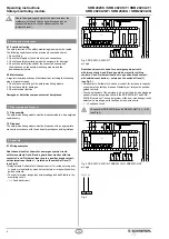
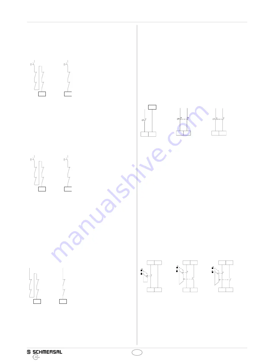
External reset button (Fig. 5)
•
The external reset button is wired to the terminals X1 (without edge
detection for switch-off level 1) and X2 (without edge detection for
switch-off level 2).
•
The external reset button is integrated in the feedback circuit in series.
K
A
K
B
24 VDC
J
J
X2
24 VDC
K
C
K
D
K
C
K
D
X1
Fig. 5
left = switch-off level 1
right = switch-off level 2 (SRB 202CA, SRB 202CS and SRB 202CA/Q)
External reset button (Fig. 6)
•
The external reset button is wired to the terminals X1 (with edge
detection for switch-off level 1) and X2 (without edge detection for
switch-off level 2).
•
The external reset button is integrated in the feedback circuit in series.
* Automatic start at switch-off level 2: the reset button
J
must be
replaced with a bridge.
K
A
K
B
24 VDC
J
J
X2
*
24 VDC
K
C
K
D
K
C
K
D
X1
Fig. 6
left = switch-off level 1
right = switch-off level 2 (SRB 202CA/T, SRB 202CS/T and SRB 202CA/QT)
Automatic start (see Fig. 7)
•
The automatic start is programmed by connecting the feedback
circuit to the terminals X1 (referring to the switch-off level 1) and X2
(referring to the switch-off level 2). Feedback circuits are not required
to be replaced by a bridge.
•
When the safety-monitoring module is used with the operating mode
“Automatic start”, an automatic restart after a shutdown in case of
emergency must be prevented by the upstream control to EN 60204-1
paragraph 9.2.5.4.2 and 10.8.3.
* An external reset button for a manual start can be installed in
switch-off level 2.
K
A
K
B
24 VDC
X2
*
24 VDC
K
C
K
D
K
C
K
D
X1
Fig. 7
left = switch-off level 1
right = switch-off level 2 (SRB 202CA, SRB 202CS and SRB 202CA/Q)
8.3
Sensor configuration
8.3.1 Sensor configuration superordinated switch-off level 1
Single-channel emergency stop circuit with command devices
to DIN EN ISO 13850 (EN 418) and EN 60947-5-5 (Fig. 8)
•
Wire breakage and earth leakage in the control circuits are detected.
Dual-channel emergency stop circuit with command devices
to DIN EN ISO 13850 (EN 418) and EN 60947-5-5 (Fig. 9)
•
Wire breakage and earth leakage in the control circuits are detected.
•
Cross-wire shorts between the control circuits
are not detected.
Dual-channel emergency stop circuit with command devices
to DIN EN ISO 13850 (EN 418) and EN 60947-5-5 (Fig. 10)
•
Wire breakage and earth leakage in the control circuits are detected.
•
Cross-wire shorts between the control circuits are detected.
S12
S22
S12
24 VDC
S12
S22
24 VDC
24 VDC
S12
S22
24 VDC
0 VDC
Fig. 8
SRB 202CA,
SRB 202CS,
SRB 202CA/T,
SRB 202CS/T
Fig. 9
SRB 202CA,
SRB 202CS,
SRB 202CA/T,
SRB 202CS/T
Fig. 10
SRB 202CA/Q,
SRB202CA/QT
8.3.2 Sensor configuration, partially functioning switch-off level 2
Single-channel guard door monitoring circuit with interlocking
devices to EN 1088 (Fig. 11)
•
With one positive-break position switch.
•
Wire breakage and earth leakage in the control circuits are detected.
Dual-channel guard door monitoring circuit with interlocking
device to EN 1088 (Fig. 12)
•
With at least one positive-break position switch
•
The control system recognises wire-breakage and earth faults in
the control circuit.
•
Cross-wire shorts between the control circuits
are not detected.
Dual-channel guard door monitoring circuit with interlocking
device to EN 1088 (Fig. 13)
•
With at least one positive-break position switch
•
The control system recognises wire-breakage and earth faults in
the control circuit.
•
Cross-wire shorts between the control circuits are detected.
S32
S31
S42
S32
S32
S31
S42
S41
S32
S31
S44
S43
Fig. 11
SRB 202CS,
SRB 202CS/T
Fig. 12
SRB 202CS,
SRB 202CS/T
Fig. 13
SRB 202CA,
SRB 202CA/T,
SRB 202CA/Q,
SRB 202CA/QT

