4
Operating instructions
Safety-monitoring module
SRB 202MSK /
SRB 202MSK/QS
EN
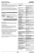
6 Set-up and maintenance
6.1 Functional testing
The safety function of the safety-monitoring module must be tested.
The following conditions must be previously checked and met:
1. Correct ixing
2. Check the integrity of the cable entry and connections
3. Check the safety-monitoring module’s enclosure for damage.
4. Check the electrical function of the connected sensors and
their inluence on the safety-monitoring module and the
downstream actuators
6.2 Maintenance
A regular visual inspection and functional test, including the following
steps, is recommended:
1. Check the correct ixing of the safety-monitoring module
2. Check the cable for damages
3. Check electrical function
Damaged or defective components must be replaced.
7 Disassembly and disposal
7.1 Disassembly
The safety-monitoring module must be disassembled in a de-energised
condition only.
7.2 Disposal
The safety-monitoring module must be disposed of in an appropriate
manner in accordance with the national prescriptions and legislations.
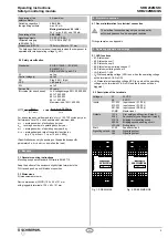
5.3 Set-up instructions
The signalling output L84 is used to signal a defective muting lamp.
To set this signalling output, the following steps must be executed:
• Prior to switching the supply voltage (24 VDC) on, check the proper
connection of the SRB 202MSK / SRB 202MSK/QS and connect a
muting lamp to the outputs LA1 and LA2 (min. 100 mA, max. 500 mA).
•
The enclosure must be opened to set the signalling output L84. To open
the front cover, insert a slot screwdriver in the top and bottom cover
notch and gently lift it (Fig. 3 and 4). When the front cover is open, the
electrostatic discharge requirements must be respected and observed.
After the setting, the front cover must be itted back in position.
•
Bring the SRB 202MSK / SRB 202MSK/QS in muting condition
(actuate the sensors S1 and S2 within the timeframe).
•
Check if the muting lamp is on.
•
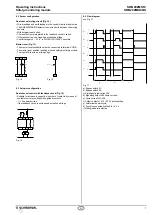
Connect a voltmeter to output L84 and the 0V potential and turn
the lamp trimmer R1 (Fig. 5) until the signal condition of output L84
changes from 24V to 0V.
•
Remove the muting lamp at the outputs LA1 and LA2. The signal
condition of output L84 changes to 24 V. Reconnect the muting lamp.
•
The set lamp current must be entered on the front cover.
U
B
U
i
K1
K2
K3
K4
K5
LA
A1 X1 X2 MR
S11 S12 S13
S22
S21
S23
X23 L84 X13
24
LA1 13 23 L54
LA2 14
A2
SRB 202MSK
L84: ……. A
U
B
U
i
K1
K2
K3
K4
K5
LA
A1 X1 X2 MR
S11 S12 S13
S22
S21
S23
X23 L84 X13
24
LA1 13 23 L54
LA2 14
A2
SRB 202MSK
L84: ……
…
… . A
U
B
U
i
K1
K2
K3
LA
A1 X1 X2 MR
S11 S12 S13
S22
S21
S23
X23 L84 X13
24
LA1 13 23 L54
LA2 14
A2
SRB 202MSK/QS
L84: ……. A
U
B
U
i
K1
K2
K3
LA
A1 X1 X2 MR
S11 S12 S13
S22
S21
S23
X23 L84 X13
24
LA1 13 23 L54
LA2 14
A2
SRB 202MSK/QS
L84: ……
…
… . A
Fig. 3: SRB 202MSK
Fig. 4: SRB 202MSK/QS
R1
Fig. 5


