5
SRB 202MSK /
SRB 202MSK/QS
Operating instructions
Safety-monitoring module
EN
8 Appendix
8.1 Wiring examples
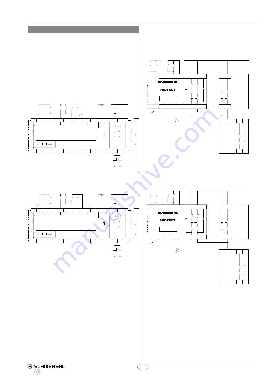
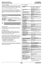
Dual-channel control, shown for 2 muting sensors and an external
master reset button
J
(Fig. 6 and 7)
•
Relay outputs: 2-channel control, suitable for increase incapacity or
number of contacts by means of contactors or relays with positive-
guided contacts.
•
The control system recognises wire-breakage and earth faults in
the monitoring circuit.
•
Only SRB 202MSK/QS: Cross-wire shorts between the monitoring
circuits are detected.
•
Electronic fuse F1: 1.25 A
•
S
= Feedback circuit
K1
K2
K3
F1
A1
L
N
K
A
K
A
K1
K2
K3
K
A
K
B
S1
S
S2
S4
S3
A2
L54
LA1 LA2 X13
14
13
24
23
X23
b)
Master-
J
a)
S11
+
+
–
–
S12
S13
S21
S22 S23 L84
MR
X1
X2
K
B
K
B
F3
F2
Fig. 6: SRB 202MSK
a) Muting sensors
b) Logic and lamp monitoring
K1
K2
K3
F1
A1
L
N
K
A
K
A
K1
K2
K3
K
A
K
B
S1
S
S2
S4
S3
A2
L54
LA1 LA2 X13
14
13
24
23
X23
b)
Master-
J
a)
S11
+
+
–
–
S12
S13
S21
S22 S23 L84
MR
X1
X2
K
B
K
B
F3
F2
Fig. 7: SRB 202MSK/QS
a) Muting sensors
b) Logic and lamp monitoring
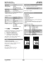
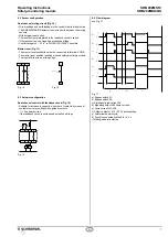
Wiring example AOPD* with relay outputs or semi-conductor
outputs (Fig. 8 to 13)
* Active Optoelectronic Protective Device, e.g. safety light grids etc.,
formerly also known as ESD (= electro-sensitive safety device)
X1
S11
S1
S3
S2
S4
K1
K2
K3
X2
a)
c)
+24 V
b)
S12
LA1
S21
LA2
S22 X13
14
13
24
23 X23
U
B
U
i
K1
K2
K3
LA
SRB 202MSK
L84: ……. A
d)
Fig. 8: SRB 202MSK
a) Muting sensors,
b) Bridge;
c) AOPD (relay outputs);
d) Elan safety relay
X1
S11
S1
S3
S2
S4
K1
K2
K3
X2
a)
c)
+24 V
b)
S12
LA1
S22
LA2
S23 X13
14
13
24
23 X23
U
B
U
i
K1
K2
K3
LA
SRB 202MSK/QS
L84: ……. A
d)
Fig. 9: SRB 202MSK/QS
a) Muting sensors,
b) Bridge;
c) AOPD (relay outputs);
d) Elan safety relay


