6
Operating instructions
Safety-monitoring module
SRB 202MSL
EN
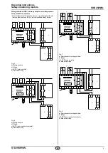
8.2 Sensor configuration
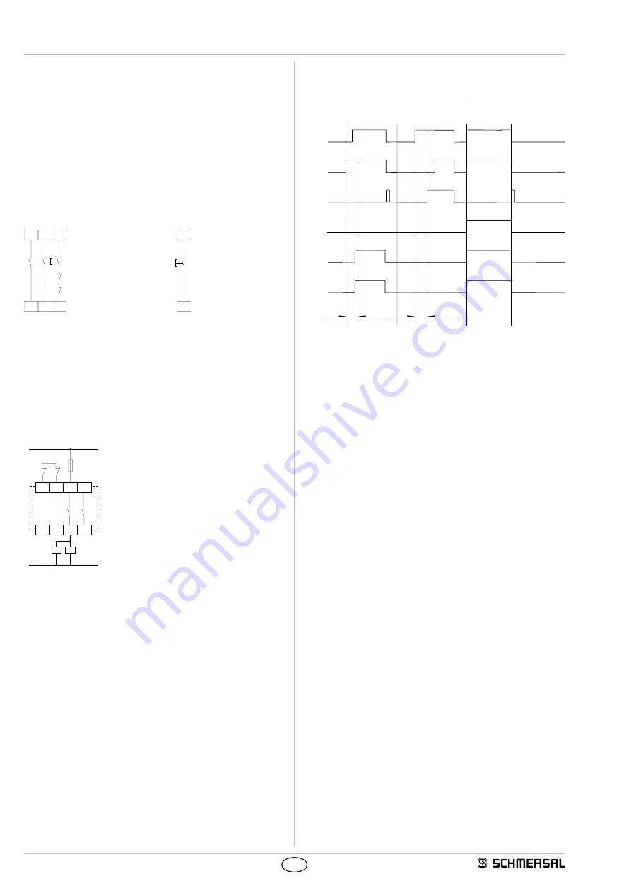
Dual-channel muting circuit (Fig. 9)
• Wire breakage and earth leakage in the control circuits are detected.
• Cross-wire shorts between the muting sensors are detected.
• With external reset button
• The reset button is integrated in the feedback circuit in series.
• If the reset button is not required, establish a bridge.
• Category 4 – PL e to DIN EN ISO 13849-1 possible.
Master reset (Fig. 10)
• The master reset pushbutton must be connected to terminal X1-MR.
• The master reset enables resetting a locked safety-monitoring
module. The input MR reacts on a rising edge.
S12
S11
S1
K
A
K
B
S23
S22
S2
X2
X1
J
MR
X1
Master-
J
Fig. 9
Fig. 10
8.3 Actuator configuration
Dual-channel control with feedback circuit (Fig. 11)
• Suitable for increase in capacity or number of contacts by means of
contactors or relays with positive-guided contacts.
•
S
= feedback circuit:
If the feedback circuit is not required, establish a bridge.
X1 X2 13
23
24
14
K
A
S
L1
N
K
B
K
A
K
B
Fig. 11
8.4 Flow diagram
see Fig. 12
f)
e)
d)
c)
b)
a)
1
1
0
0
1
0
1
0
1
0
t
S
t
S
i)
h)
g)
Fig. 12
a) Bypass switch S1;
b) Bypass switch S2;
c) Simultaneity indication L54;
d) Signalling output L84 (lamp current);
e) Lamp current LA1-LA2;
f) Output contacts 13-14 / 23-24 potential-free;
g) uninterrupted workcycle;
h) Synchronous actuation fault t
s
> 2.5 s
i) Muting indicator defective


