3
SRB 207AN-230V
Operating instructions
Safety-monitoring module
EN
3. Mounting
3.1 General mounting instructions
Mounting: snaps onto standard DIN rails to EN 60715.
3.2 Dimensions
Device dimensions (H/W/D): 100 x 45 x 121 mm
4. Electrical connection
4.1 General information for electrical connection
As far as the electrical safety is concerned, the protection
against unintentional contact of the connected and therefore
electrically interconnected apparatus and the insulation of the
feed cables must be designed for the highest voltage, which
can occur in the device.
The electrical connection may only be carried out by
authorised personnel in a de-energised condition.
Wiring examples: see appendix
5. Operating principle and settings
5.1 Operating principle after the operating voltage is switched on
With the guard door closed or the emergency stop command devices
unlocked, the enabling paths are closed as soon as the start button is
pushed. During the start command, the falling edge is detected, when
the contacts of the downstream relays acting on the feedback circuit
are closed.
If the safety guard is opened or the emergency-stop button is actuated,
the enabling paths of the safety-monitoring module will open.
The machine is stopped and the LED K1 and K2 will go out.
The corresponding signal output signals which guard was opened.
Inputs S11/S12-S22/S73/S74;
S31/S32-S42/S83/S84;
S51/S52-S62/S93/S94
Safety switches or emergency stop command devices with one NC
and one NO contact must be connected to the inputs. If not all inputs
are wired, a bridge must be established between Sx1 and Sx2 of the
non-used input.
Start button/Feedback loop: X1/X2
Connect start button/feedback circuit to the inputs X1 and X2 according
to the wiring diagram
Automatic start X1-X3
The automatic start is programmed by connecting the feedback circuit
to the terminals X1-X3. If no start button and no feedback circuit is
used, a bridge must be established between X1 and X3.
Outputs
Enabling paths 13-14, 23-24: NO contacts for safety function
Signalling output Y1-Y6
0 V
safety guard open / no enabling signal
24 V
safety guard closed / enabling signal
Auxiliary contact A1.1-32
Conditions of the enabling paths
Signalling outputs must not be used in safety circuits.
Due to the operating principle of the electronic fuse, the
customer must check that no hazard is caused by an
unexpected restart in circuits without reset button
(automatic reset).
6. Set-up and maintenance
6.1 Functional testing
The safety function of the safety-monitoring module must be tested.
The following conditions must be previously checked and met:
1. Fitting of the safety monitoring module
2. Fitting and integrity of the power cable
6.2 Maintenance
In the case of correct installation and adequate use, the safety-
monitoring module features maintenance-free functionality.
A regular visual inspection and functional test, including the following
steps, is recommended:
• Check the correct fixing of the safety-monitoring module
• Check the cable for damage.
If a manual functional check is necessary to detect a possible
accumulation of faults, then this must take place during the
intervals noted as follows:
• at least every month for PL e with category 3 or
category 4 (according to ISO 13849-1) or SIL 3 with HFT
(hardware fault tolerance) = 1 (according to IEC 62061);
• at least every 12 months for PL d with category 3
(according to ISO 13489-1) or SIL 2 with HFT
(hardware fault tolerance) = 1 (according to IEC 62061).
Damaged or defective components must be replaced.
7. Disassembly and disposal
7.1 Disassembly
The safety-monitoring module must be disassembled in a de-energised
condition only.
7.2 Disposal
The safety-monitoring module must be disposed of in an appropriate
manner in accordance with the national prescriptions and legislations.
8. Appendix
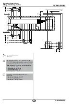
8.1 Wiring example
The application examples shown are suggestions. They however do not
release the user from carefully checking whether the switchgear and its
set-up are suitable for the individual application
The wiring diagram is shown with guard doors closed and in a
de-energised condition. Inductive loads (e.g. contactors, relays, etc.)
are to be provided with suitable interference suppression circuitry.
Do not connect additional loads to terminal S..

