5
SRB 211AN V.2 / CC V.2 / PC V.2
Operating instructions
Safety-monitoring module
EN
5.4 Setting report SRB 211 AN
This report regarding the setting of the device must be completed
accordingly by the customer and enclosed in the technical manual of
the machine.
The setting report must be available whenever a safety check is performed.
Company:
The safety-monitoring module is used in the following machine:
Machine n°
Machine type
Module n°
Set drop-out delay:
Set on (date)
Signature of the responsible person
6. Set-up and maintenance
6.1 Functional testing
The safety function of the safety-monitoring module must be tested.
The following conditions must be previously checked and met:
1. Correct fixing
2. Check the integrity of the cable entry and connections
3. Check the safety-monitoring module's enclosure for damage.
4. Check the electrical function of the connected sensors and
their influence on the safety-monitoring module and the
downstream actuators
6.2 Maintenance
A regular visual inspection and functional test, including the following
steps, is recommended:
1. Check the correct fixing of the safety-monitoring module
2. Check the cable for damages
3. Check electrical function
4. Check drop-out delay
The device has to be integrated into the periodic check-ups
according to the Ordinance on Industrial Safety and Health,
however at least 1 × year.
Damaged or defective components must be replaced.
7. Disassembly and disposal
7.1 Disassembly
The safety-monitoring module must be disassembled in a de-energised
condition only. Push up the bottom of the enclosure and hang out
slightly tilted forwards.
7.2 Disposal
The safety-monitoring module must be disposed of in an appropriate
manner in accordance with the national prescriptions and legislations.
8. Appendix
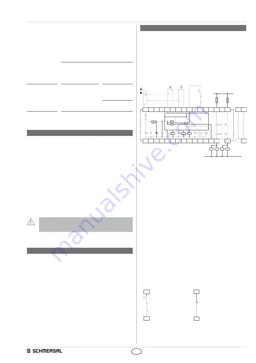
8.1 Wiring examples
Dual-channel control, shown for a guard door monitor; with two
contacts A and B, where at least one is a positive break contact;
with external reset button
J
(see Fig. 8)
• Relay outputs: Suitable for 2-channel control, for increase in capacity
or number of contacts by means of contactors or relays with positive-
guided contacts.
• The control system recognises wire-breakage, earth faults and cross-
wire shorts in the monitoring circuit.
K3
K2
K1
K4
F1*
F2**
F4*
F3*
A1
L1
N
K
B
K
A
K1
K
B
K
A
K2
24
38
14
13
23
37
Timer
a)
J
S
UB
Ui
Y1
S22
S13 S14
X1
X2
X3
S21
K
A
K
B
K
D
K
C
K
C
K
D
K3
K4
A2
Fig. 8
a) Logic
*
Electronic fuse
** Hybrid fuse
S
Feedback circuit
8.2 Start configuration
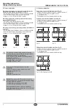
External reset button (with edge detection) (see Fig. 9)
• The external reset button is integrated as shown.
• The safety-monitoring module is activated by the reset (after release)
of the reset button (= detection of the trailing edge). Faults in the reset
button, e.g. welded contacts or manipulations which could lead to an
inadvertent restart, are detected in this configuration and will result in
an inhibition of the operation.
Automatic start (see Fig. 10)
• The automatic start is programmed by connecting the feedback circuit
to the terminals. If the feedback circuit is not required, establish a
bridge.
•
Caution:
Not admitted without additional measure due to the risk of
gaining access by stepping behind!
•
Caution: Within the meaning of EN IEC 60204-1 paragraph 9.2.5.4.2
and 10.8.3, the operating mode "automatic start" is only restrictedly
admissible. In particular, any inadvertent restart of the machine must
be prevented by other suitable measures.
K
B
J
S
K
A
X2
X1
K
B
S
K
A
X3
X1
Fig. 9
Fig. 10

