6
Operating instructions
Safety-monitoring module
SRB 211AN V.2 / CC V.2 / PC V.2
EN
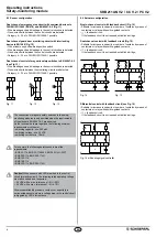
8.3 Sensor configuration
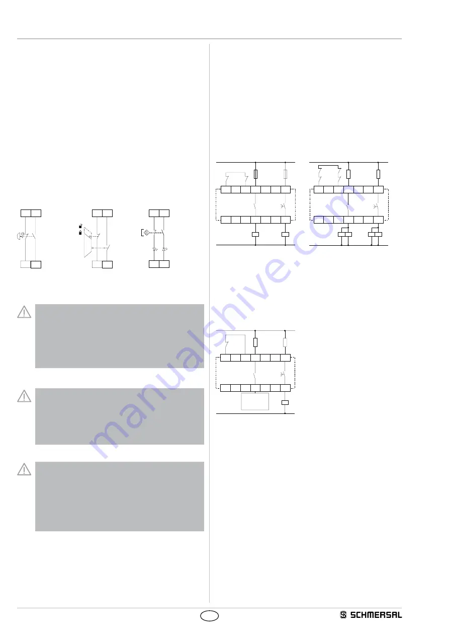
Dual-channel emergency stop circuit with command devices to
DIN EN ISO 13850 (EN 418) and EN 60947-5-5 (Fig. 11)
• Wire breakage and earth leakage in the control circuits are detected.
• Cross-wire shorts between the control circuits are detected.
• Category 4 – PL e to DIN EN ISO 13849-1 possible.
Dual-channel guard door monitoring circuit with interlocking
device to EN 1088 (Fig. 12)
• With at least one positive-break position switch
• Wire breakage and earth leakage in the control circuits are detected.
• Cross-wire shorts between the control circuits are detected.
• Category 4 – PL e to DIN EN ISO 13849-1 possible.
Dual-channel control of magnetic safety switches to EN 60947-5-3
(see Fig. 13)
• Wire breakage and earth leakage in the control circuits are detected.
• Cross-wire shorts between the monitoring circuits are detected.
• Category 4 – PL e to DIN EN ISO 13849-1 possible.
S22
S21
S14
S13
S22
S21
S14
S13
S22 S14
S21
S13
Fig. 11
Fig. 12
Fig. 13
The connection of magnetic safety switches to the safety-
monitoring modules is only admitted when the requirements
of the standard EN 60 947-5-3 are observed.
As the technical data are regarded, the following minimum
requirements must be met:
– switching capacity: min. 240 mW
– switching voltage: min. 24 VDC
– switching current: min. 10 mA
For example, the following safety sensors meet the
requirements:
– BNS 33-11z, BNS 33-11z-2063, BNS 33-11zG-2237
– BNS 250-11z, BNS 250-11zG
– BNS 120-11z
– BNS 180-11z
– BNS 303-11z, BNS 303-11zG
Caution!
When sensors with LED are wired in the control
circuit (protective circuit), the following rated operating voltage
must be observed and respected:
– 24 VDC with a max. tolerance of –5 %/+20 %
– 24 VAC with a max. tolerance of –5 %/+10 %
Otherwise availability problems could occur, especially in
series-wired sensors, where a voltage drop in the control circuit
is triggered by LED's for instance
8.4 Actuator configuration
Single-channel control with feedback circuit (Fig. 14)
• Suitable for increase in capacity or number of contacts by means of
contactors or relays with positive-guided contacts.
•
S
= feedback circuit:
If the feedback circuit is not required, establish a bridge.
Dual-channel control with feedback circuit (Fig. 15)
• Suitable for increase in capacity or number of contacts by means of
contactors or relays with positive-guided contacts.
•
S
= feedback circuit:
If the feedback circuit is not required, establish a bridge.
X1
X3
37
13
38
14
K
C
K
A
S
L1
N
K
A
K
C
X1
X3
37
13
38
14
K
B
K
C
K
D
K
A
K
B
L1
N
K
A
K
D
K
C
S
Fig. 14
Fig. 15
Differential control with feedback circuit (see Fig. 16)
• Suitable for increase in capacity or number of contacts by means of
contactors or relays with positive-guided contacts.
•
S
= feedback circuit:
If the feedback circuit is not required, establish a bridge.
X1
X3
37
13
38
14
K
A
L1
N
K
A
S
a)
Fig. 16 a) Enabling signal controller

