4
Operating instructions
Safety-monitoring module
SRB 302X3
EN
6. Set-up and maintenance
6.1 Functional testing
The safety function of the safety-monitoring module must be tested.
The following conditions must be previously checked and met:
1. Correct fixing
2. Check the integrity of the cable entry and connections
3. Check the safety-monitoring module's enclosure for damage.
4. Check the electrical function of the connected sensors and their influ-
ence on the safety-monitoring module and the downstream actuators
6.2 Maintenance
A regular visual inspection and functional test, including the following
steps, is recommended:
1. Check the correct fixing of the safety-monitoring module
2. Check the cable for damages
3. Check electrical function
The device has to be integrated into the periodic check-ups
according to the Ordinance on Industrial Safety and Health,
however at least 1 × year.
Damaged or defective components must be replaced.
7. Disassembly and disposal
7.1 Disassembly
The safety-monitoring module must be disassembled in a de-energised
condition only. Push up the bottom of the enclosure and hang out
slightly tilted forwards.
7.2 Disposal
The safety-monitoring module must be disposed of in an appropriate
manner in accordance with the national prescriptions and legislations.
8. Appendix
8.1 Wiring examples
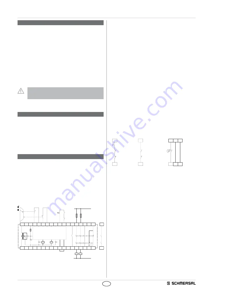
Dual-channel control, shown for a guard door monitor with
two position switches where one has a positive break contact;
with external reset button
J
(Fig. 2)
• Relay outputs: Suitable for 2-channel control, for increase in capacity
or number of contacts by means of contactors or relays with
positive-guided contacts.
• The control system recognises wire breakage, earth faults and
cross-wire shorts in the monitoring circuit.
•
S
= Feedback circuit
K
A
K
B
K1
K2
F1
UB
S21
A1
S22
S31
S32
K
A
K
B
L1
N
K
A
K
B
K1
K2
Y31
13
23
S13
S14
A2
S12
S11
Y32
14
24
33
34
42
41
B1
B2
S33
S34
a)
S
J
Fig. 2 a) channel control
8.2 Start configuration
External reset button (with edge detection) (see Fig. 3)
• The external reset button is integrated in the feedback circuit in series.
• The safety-monitoring module is activated by the reset (after release)
of the reset button (= detection of the trailing edge). Faults in the reset
button, e.g. welded contacts or manipulations which could lead to an
inadvertent restart, are detected in this configuration and will result in
an inhibition of the operation.
Automatic start (see Fig. 4)
• The automatic start is programmed by connecting the feedback circuit
to the terminals.
• Caution: Not admitted without additional measure due to the risk of
gaining access by stepping behind!
• Caution: Within the meaning of EN IEC 60204-1 paragraph 9.2.5.4.2
and 10.8.3, the operating mode "automatic start" is only restrictedly
admissible. In particular, any inadvertent restart of the machine must
be prevented by other suitable measures.
Feedback loop (Fig. 3 and 4)
• The feedback circuit is integrated as shown.
• If the feedback circuit is not required, establish a bridge (Fig. 4)
8.3 Sensor configuration
Single-channel emergency stop circuit with command devices to
DIN EN ISO 13850 (EN 418) and EN 60947-5-5 (Fig. 5)
• Wire breakage and earth leakage in the control circuits are detected.
• Control category: 2 to EN 954-1
• Category 2 – PL d to DIN EN 13849-1 possible
S34
S33
K
A
J
K
B
S14
S13
K
A
K
B
S12
S11
S22
S21
S32
S31
Fig. 3
Fig. 4
Fig. 5
Dual-channel emergency stop circuit with command devices to
DIN EN ISO 13850 (EN 418) and EN 60947-5-5 (Fig. 6)
• The control system recognises wire-breakage and earth faults in the
control circuit.
• Cross-wire shorts between the control circuits are detected.
• Control category: 4 to EN 954-1
• Category 4 – PL e to DIN EN ISO 13849-1 possible.
Single-channel guard door monitoring circuit with interlocking
devices to EN 1088 (Fig. 7)
• At least one contact with positive break required.
• Wire breakage and earth leakage in the control circuits are detected.
• Control category: 2 to EN 954-1
• Category 2 – PL d to DIN EN ISO 13849-1 possible.


