5
SRB 302X3
Operating instructions
Safety-monitoring module
EN
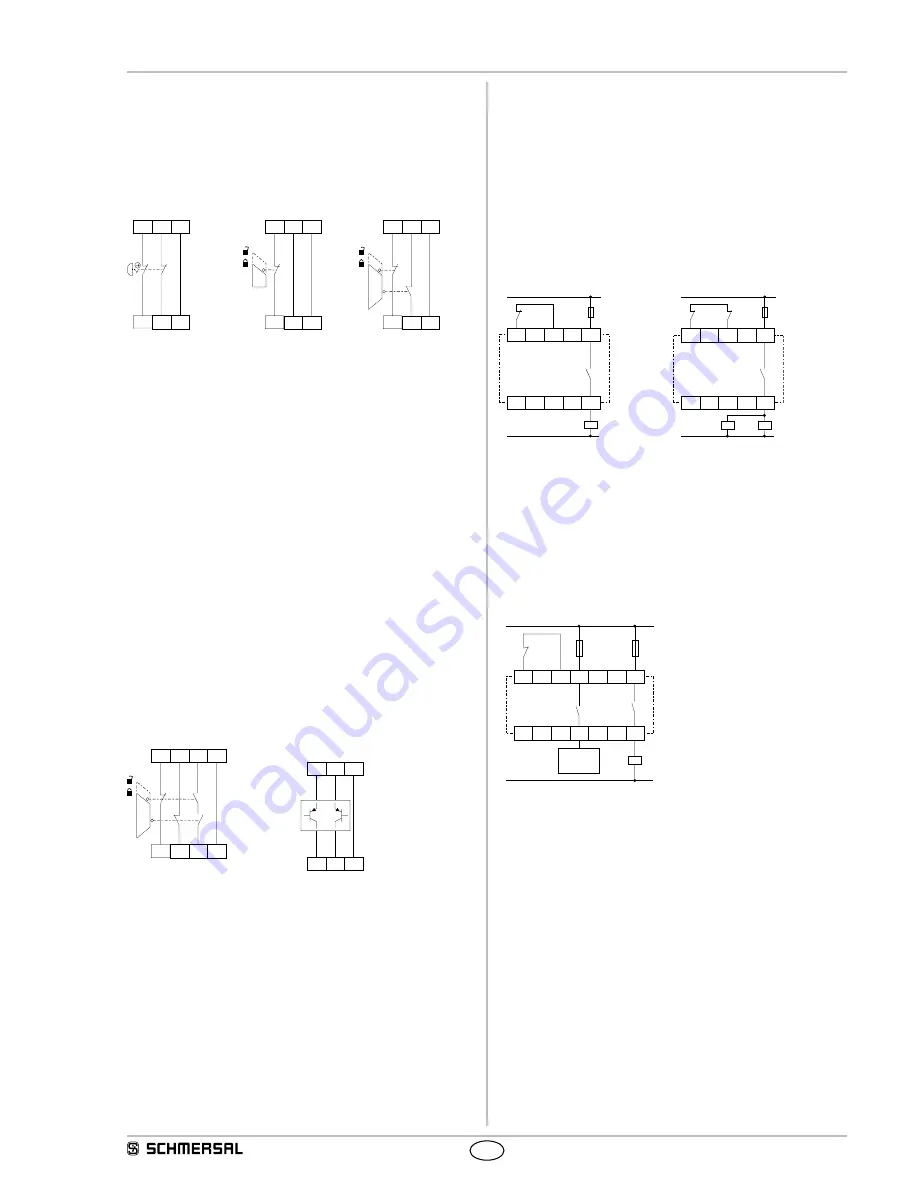
Dual-channel guard door monitoring circuit with interlocking
device to EN 1088 (see Fig. 8)
• With at least one positive-break position switch
• The control system recognises wire-breakage and earth faults in the
control circuit.
• Cross-wire shorts between the control circuits are detected.
• Control category: 4 to EN 954-1
• Category 4 – PL e to DIN EN 13849-1 possible
S22
S21
S32
S31
S12
S11
S12
S11
S22
S21
S32
S31
S22
S21
S32
S31
S12
S11
Fig. 6
Fig. 7
Fig. 8
Monitored dual-channel controled safety guard (Fig. 9)
• Dual-channel safety guard monitoring to EN 1088 with at least one
positive-break position switch and automatic start
• The control system recognises wire-breakage and earth faults in the
control circuit.
• Cross-wire shorts between the control circuits are detected.
• A time of approx. 500 ms is tolerated between the opening of the
contacts S13-S14 and the closing of S21-S22 and S31-S32.
• Control category: 4 to EN 954-1
• Category 4 – PL e to DIN EN 13849-1 possible
Dual-channel control of a safety-related electronic (micro-
processor-based) safety guard with p-type transistor outputs
e.g. AOPD's to EN IEC 61496 (see Fig. 10)
• The control system recognises wire-breakage and earth faults in the
control circuit.
• Cross-wire shorts between the control circuits are not detected.
It's monitored on the sensor level.
• Clip S11 have to be used for p-type sensors.
• Control category: 3 to EN 954-1
• If cross-wire shorts in the control circuits are detected by the
safety guard:
- control category 4 to EN 954-1
- category 4 – PL e to DIN EN ISO 13849-1 possible
S22
S21
S32
S31
S14
S13
S12
S11
S12 S32
+24V +24V
S22
S21
S11
S11
Fig. 9
Fig. 10
8.4 Actuator configuration
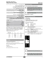
Single-channel control with feedback circuit (Fig. 11)
• Suitable for increase in capacity or number of contacts by means of
contactors or relays with positive-guided contacts.
•
S
= feedback circuit:
If the feedback circuit is not required, establish a bridge.
Dual-channel control with feedback circuit (Fig. 12)
• Suitable for increase in capacity or number of contacts by means of
contactors or relays with positive-guided contacts.
•
S
= feedback circuit:
If the feedback circuit is not required, establish a bridge.
14
S33
S34
13
K
A
K
A
L1
N
*
14
S33
S34
13
K
B
K
A
L1
N
K
B
K
A
*
Fig. 11
Fig. 12
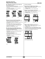
Differential control with feedback circuit (see Fig. 13)
• Suitable for increase in capacity or number of contacts by means of
contactors or relays with positive-guided contacts.
•
S
= feedback circuit:
If the feedback circuit is not required, establish a bridge. If the ena-
bling circuit of the controller must be equipped with its own feedback
circuit, this circuit must be integrated as shown in the wiring example
"dual-channel control with feedback circuit" (see there).
S33
S34
23
13
24
14
K
A
L1
N
K
A
S
a)
Fig. 13 a) Enabling signal controller


