5
SRB 304ST
Operating instructions
Safety-monitoring module
EN
8. Appendix
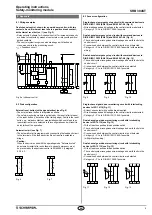
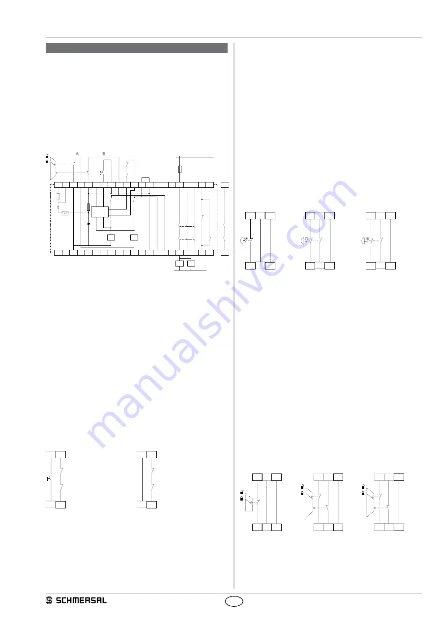
8.1 Wiring examples
Dual-channel control, shown for a guard door monitor; with two
contacts A and B, where at least one is a positive break contact;
with external reset button
J
(see Fig. 5)
• Relay outputs: Suitable for 2-channel control, for increase in capacity
or number of contacts by means of contactors or relays with positive-
guided contacts.
• The control system recognises wire breakage, earth faults and
cross-wire shorts in the monitoring circuit.
•
S
= Feedback circuit
A1 A1.1 S21 S22 S11 X5
J
X3 X4 S12 X1 X2 S32 S31
A2
Y3 Y2 Y1
S
K2
K2
a)
K1
K1
F2
F1
13
23 33
L1
K2
K1
K
A
K
B
K
B
K
A
K2
K1
41
14 24 34 42
Fig. 5 a) channel control
8.2 Start configuration
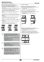
External reset button (with edge detection) (see Fig. 6)
• The external reset button is integrated as shown.
• The safety-monitoring module is activated by the reset (after release)
of the reset button (= detection of the trailing edge). Faults in the reset
button, e.g. welded contacts or manipulations which could lead to an
inadvertent restart, are detected in this configuration and will result in
an inhibition of the operation.
Automatic start (see Fig. 7)
• The automatic start is programmed by connecting the feedback circuit
to the terminals. If the feedback circuit is not required, establish a
bridge.
•
Caution:
When the device is used with the operating mode "Automatic start",
an automatic restart after a shutdown in case of emergency must
be prevented by the upstream control to EN 60204-1, paragraph
9.2.5.4.2.
X2
S
X1
X4
X3
K
A
K
B
X2
S
X1
X4
X5
K
A
K
B
Fig. 6
Fig. 7
8.3 Sensor configuration
Single-channel emergency stop circuit with command devices to
DIN EN ISO 13850 (EN 418) and EN 60947-5-5 (Fig. 8)
• Wire breakage and earth leakage in the control circuits are detected.
• Category 2 – PL d to DIN EN 13849-1 possible
Dual-channel emergency stop circuit with command devices to
DIN EN ISO 13850 (EN 418) and EN 60947-5-5 (Fig. 9)
• The control system recognises wire-breakage and earth faults in the
control circuit.
• Cross-wire shorts between the control circuits are not detected.
• Category 4 – PL e to DIN EN ISO 13849-1 possible (with protective
wiring)
Dual-channel emergency stop circuit with command devices to
DIN EN ISO 13850 (EN 418) and EN 60947-5-5 (Fig. 10)
• The control system recognises wire-breakage and earth faults in the
control circuit.
• Cross-wire shorts between the control circuits are detected.
• Category 4 – PL e to DIN EN ISO 13849-1 possible.
S12
S11
S32
S12
S22
S21
S12
S11
S32
S31
S22
S21
S12
S11
S22
S21
S32
S31
Fig. 8
Fig. 9
Fig. 10
Single-channel guard door monitoring circuit with interlocking
devices to ISO 14119 (Fig. 11)
• At least one contact with positive break required.
• Wire breakage and earth leakage in the control circuits are detected.
• Category 2 – PL d to DIN EN ISO 13849-1 possible.
Dual-channel guard door monitoring circuit with interlocking
device to ISO 14119 (see Fig. 12)
• With at least one positive-break position switch
• The control system recognises wire-breakage and earth faults in the
control circuit.
• Cross-wire shorts between the control circuits are not detected.
• Category 4 – PL e to DIN EN ISO 13849-1 possible
(with protective wiring)
Dual-channel guard door monitoring circuit with interlocking
device to ISO 14119 (see Fig. 13)
• With at least one positive-break position switch
• The control system recognises wire-breakage and earth faults in the
control circuit.
• Cross-wire shorts between the control circuits are detected.
• Category 4 – PL e to DIN EN 13849-1 possible
S12
S11
S32
S12
S22
S21
S12
S11
S32
S31
S22
S21
S12
S11
S22
S21
S32
S31
Fig. 11
Fig. 12
Fig. 13


