3
SRB 308IT
Operating instructions
Safety-monitoring module
EN
Outputs
Number of safety contacts:
3
Number of auxiliary contacts:
2
Number of signalling outputs:
6
Switching capacity of
the safety contacts:
13-14; 23-24; 33-34:
max. 250 V, 6 A ohmic (inductive in
case of appropriate protective wiring)
min. 10 V / 10 mA
Switching capacity of
the auxiliary contacts:
41-42 / 53-54:
24 VDC / 2 A
Switching capacity of
the signalling outputs:
24 VDC: max. 10 mA
Fuse rating of the
safety contacts:
6.3 A slow blow
Recommended fuse for
the auxiliary contacts:
2 A slow blow
Fuse rating of the
signalling outputs:
Internal electronic trip F2,
tripping current > 100 mA
Utilisation category
to EN 60947-5-1:
AC-15 / DC-13: EN 60947-5-1
Dimensions (H/W/D):
100 mm × 45 mm × 121 mm
The data speciied in this manual is applicable when the component is
operated with rated operating voltage U
e
±0%.
2.5
Safety classiication
Standards:
EN ISO 13849-1, IEC 61508,
EN 60947-5-1
PL:
Stop 0: up to e
Control category:
Stop 0: up to 4
DC:
Stop 0: 99% (high)
CCF:
> 65 points
SIL:
Stop 0: up to 3
Service life:
20 years
B10d value (for one channel):
Low voltages range 20%: 20,000,000
40%: 7,500,000
60%: 2,500,000
80%: 1,000,000
Maximum load 100%: 400,000
MTTF
B
d
x
x
h
s/h
3600
d
10d
op
op
op
n
0,1 x n
op
t
cycle
For an average annual demand rate of n
op
= 126,720 cycles per year,
Performance Level PL e can be obtained at maximum load.
n
op
= average number of activations per year
d
op
= average number of operating days per year
h
op
= average number of operating hours per day
t
cycle
= average demand rate of the safety function in s
(e.g. 4 × per hour = 1 × per 15 min. = 900 s)
(Speciications can vary depending on the application-speciic
parameters h
op
, d
op
and t
cycle
as well as the load.)
3 Mounting
3.1 General mounting instructions
Mounting: snaps onto standard DIN rails to EN 60715.
Snap the bottom of the enclosure slightly tilted forwards in the
DIN rail and push up until it latches in position.
3.2 Dimensions
All measurements in mm.
Device dimensions (H/W/D): 100 x 45 x 121 mm
with plugged-in terminals: 120 × 45 × 121 mm
4 Electrical connection
4.1 General information for electrical connection
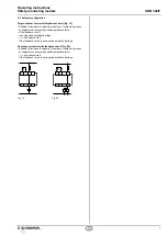
Wiring examples: see appendix
The electrical connection may only be carried out by
authorised personnel in a de-energised condition.
5 Operating principle and settings
5.1 LED functions
•
K1: Status start relay
•
K2: Status channel 1
•
K3: Status channel 2
• Ui: Status internal operating voltage (LED is on, when the
operating voltage on the terminals A1-A2 is ON and the
internal hybrid fuse has not been triggered)
• U
B
: Status operating voltage (LED is on, when the
operating voltage on the terminals A1-A2 is ON)
5.2 Terminal description
Voltages:
A1
A2
A1-A2
A1.1
+ 24 VDC / 24 VAC
0 VDC / 0 VAC
Other versions:
48 VAC / 115 VAC / 230 VAC
Supply of the semi-conductor outputs (24 VDC)
Inputs:
S11-S12
S21-S22
S31-S32
Input channel 1
Input channel 2
Input channel 2 for cross-wire detection:
Outputs:
13-14
23-24
33-34
41-42
53-54
First safety enabling circuit (stop 0)
Second safety enabling circuit (stop 0)
Third safety enabling circuit (stop 0)
Auxiliary NC contact
Auxiliary NO contact
Start:
X1-X2
X3
X4
X5
X6
Feedback circuit
Supply start
Manual start (reset button)
Automatic start
Endless time offset
Signalling
outputs:
Y1
Y2
Y3
Y4
Y5
Y6
Operating voltage
Internal voltage
Status channel 1
Status channel 2
Status feedback circuit
Status start relay (K1)
DIP switch
AF:
1
0
Monitored start
Automatic start

