4
Operating instructions
Safety-monitoring module
SRB 308IT
EN
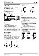
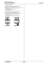
Setting the switch (see Fig. 3)
•
The "automatic start" or "trailing edge" function is programmed
by means of the switch underneath the front cover of the safety-
monitoring module.
•
The switch must only be operated in de-energised condition by
means of a inger or an insulated blunt tool.
• Pos. AF = 1 (LHS, condition on delivery): the external reset button
is monitored for a "trailing edge".
• Pos. AF = 0 (RHS): "automatic start" programmed
Only touch the components after electrical discharge!
AF
1
0
Fig. 3
Condition on delivery AF = 1
6 Set-up and maintenance
6.1 Functional testing
The safety function of the safety-monitoring module must be tested.
The following conditions must be previously checked and met:
1. Correct ixing
2. Check the integrity of the cable entry and connections
3. Check the safety-monitoring module's enclosure for damage.
4. Check the electrical function of the connected sensors and
their inluence on the safety-monitoring module and the
downstream actuators
6.2 Maintenance
A regular visual inspection and functional test, including the following
steps, is recommended:
1. Check the correct ixing of the safety-monitoring module
2. Check the cable for damages
3. Check electrical function
Damaged or defective components must be replaced.
7 Disassembly and disposal
7.1 Disassembly
The safety-monitoring module must be disassembled in a de-energised
condition only.
7.2 Disposal
The safety-monitoring module must be disposed of in an appropriate
manner in accordance with the national prescriptions and legislations.
5.3 Notes
Indications
Status
A
Module
off
B
Module
off
C
Module
started
D
Module
started
E
Module
on
Y1 – Operating
voltage
1
1
1
1
1
Y2 – Internal
voltage
1
1
1
1
1
Y3 – Channel 1
(S11-S12)
0
1
1
1
1
Y4 – Channel 2
(S21-S22, S31-S32)
0
1
1
1
1
Y5 – Feedback
circuit
1
1
1
1
0
Y6 – Relays K1
0
0
0
1
0
41-42 – Auxiliary
NC contact
1
1
1
1
→
0
0
53-54 - Auxiliary
NO contact
0
0
0
0
→
1
1
•
A: operating voltage is on, safety guard open, feedback circuit closed
•
B: operating voltage is on, safety guard closed, feedback circuit
closed
•
C: operating voltage is on, safety guard closed, feedback circuit
closed, reset button actuated
•
D: operating voltage is on, safety guard closed, feedback circuit
closed, reset button released
•
E: operating voltage is on, safety guard closed, feedback circuit open
Opening the front cover (see Fig. 2)
•
To open the front cover, insert a slot screwdriver in the top and
bottom cover notch and gently lift it.
•
When the front cover is open, the electrostatic discharge requirements
must be respected and observed.
• After the setting, the front cover must be itted back in position.
Only touch the components after electrical discharge!
K3
K2
K1
Ui
UB
S31 S32 X6 X4
S22 S21
S11
X2
53
Y5
13 23 33 X5
X3
41
Y6
A1
Y4
54
Y2
A1.1
S12
14 24
X1
Y3
42
Y1
A2
34
SRB 308IT
K3
K2
K1
Ui
UB
S31 S32 X6 X4
S22 S21
S11
X2
53
Y5
13 23 33 X5
X3
41
Y6
A1
Y4
54
Y2
A1.1
S12
14 24
X1
Y3
42
Y1
A2
34
SRB 308IT
K3
K2
K1
Ui
UB
S31 S32 X6 X4
S22 S21
S11
X2
53
Y5
13 23 33 X5
X3
41
Y6
A1
Y4
54
Y2
A1.1
S12
14 24
X1
Y3
42
Y1
A2
34
SRB 308IT
Fig. 1
Fig. 2

