6
Operating instructions
Safety-monitoring module
SRB 308IT
EN
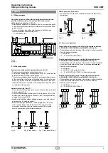
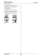
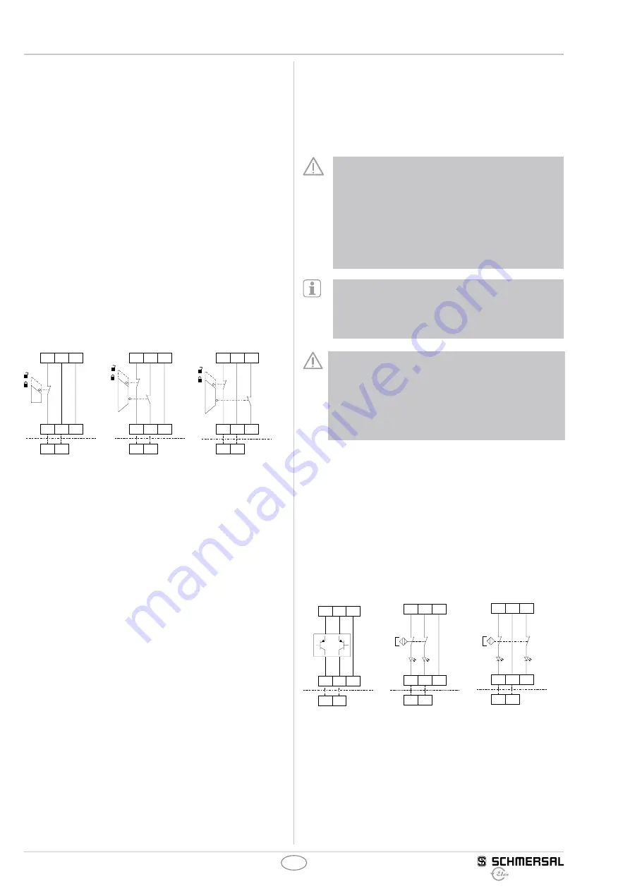
Single-channel guard door monitoring circuit with interlocking
devices to EN 1088 (Fig. 13)
•
At least one contact with positive break required
•
Wire breakage and earth leakage in the control circuits are detected.
•
Possible control categories:
– 1 to EN 954-1
– 2 – PL d to DIN EN ISO 13849-1
Dual-channel guard door monitoring circuit with interlocking
device to EN 1088 (Fig. 14)
•
At least one contact with positive break required
•
Wire breakage and earth leakage in the control circuits are detected.
•
Cross-wire shorts between the monitoring circuits are not detected.
•
Possible control categories:
– 3 to EN 954-1
– 4 to EN 954-1 (with protective wiring)
– 4 – PL e to DIN EN ISO 13849-1 (with protective wiring)
Dual-channel guard door monitoring circuit with interlocking
device to EN 1088 (Fig. 15)
•
At least one contact with positive break required
•
Wire breakage and earth leakage in the control circuits are detected.
•
Cross-wire shorts between the guard monitoring circuits are detected.
•
Possible control categories:
– 4 to EN 954-1
– 4 – PL e to DIN EN ISO 13849-1
S12
Y3
a)
S11
S22
Y4
S12
S32
S31
S12
Y3
a)
S11
S22
Y4
S21
S32
S31
S12
Y3
a)
S11
S22
Y4
S21
S32
S31
Fig. 13
Fig. 14
Fig. 15
Dual-channel control of a safety-related electronic (micro-
processor-based) safety guard with p-type transistor outputs
e.g. AOPD's to EN IEC 61496 (see Fig. 16)
•
Wire breakage and earth leakage in the control circuits are detected.
•
Cross-wire shorts between the control circuits are usually detected
by the safety guards. The safety-monitoring module therefore is not
equipped with a cross-wire short detection here.
•
Possible control categories:
– If cross-wire shorts in the control circuits are detected
by the safety guard:
– 4 to EN 954-1
– 4 – PL e to DIN EN ISO 13849-1
If cross-wire shorts in the control circuits are detected
by the safety guard.
Dual-channel control of magnetic safety switches according
to EN 60947-5-3 (see Fig. 17)
•
The control system recognises wire-breakage and earth faults in the
control circuit.
•
Cross-wire shorts between the control circuits
are not detected.
•
Possible control categories:
– 3 to EN 954-1
– 3 – PL e to DIN EN ISO 13849-1
2-channel control of magnetic safety switches according
to EN 60947-5-3 (see Fig. 15)
•
The control system recognises wire-breakage and earth faults
in the control circuit.
•
Cross-wire shorts between the control circuits are detected.
•
Possible control categories:
– 3 to EN 954-1
– 3 – PL d to DIN EN ISO 13849-1
The connection of magnetic safety switches to the
SRB 308IT safety-monitoring module is only admitted
when the requirements of the standard EN 60 947-5-3
are observed.
As the technical data are regarded, the following minimum
requirements must be met:
– switching capacity: min. 1.4 mW
– switching voltage: min. 28 VDC
– switching current: min. 50 mA
For example, the following safety sensors meet the
requirements:
– BNS 33-02z-2187
– BNS 260-02z, BNS260-02
– BNS 260-02-01z, BNS260-02-01
Caution!
When sensors with LED are wired in the control
circuit (protective circuit), the following rated operating
voltage must be observed and respected:
– 24 VDC with a max. tolerance of –5 %/+ 20 %
Otherwise availability problems could occur, especially in
series-wired sensors, where a voltage drop in the control
circuit is triggered by LED's for instance.
Dual-channel control of a safety-related electronic (micro-
processor-based) safety guard with p-type transistor outputs
e.g. AOPD's to EN IEC 61 496 (see Fig. 18)
•
Wire breakage and earth leakage in the control circuits are detected.
•
Cross-wire shorts between the control circuits are usually detected
by the safety guards. The safety-monitoring module therefore is not
equipped with a cross-wire short detection here.
•
Control category: 3 to EN 954-1:1997
•
If cross-wire shorts in the control circuits are detected
by the safety guard:
– control category 4 to EN 954-1:1997
– control category 4 – PL e to DIN EN ISO 13 849-1 possible.
S12
Y3
a)
S11
+24V +24V
S22
Y4
S21
S32
S31
S12
Y3
a)
S11
S22
Y4
S12
S32
S31
S12
Y3
a)
S11
S22
Y4
S12
S32
S31
Fig. 16
Fig. 17
Fig. 18

