5
SRB 400NE
SRB 402NE
Operating instructions
Safety-monitoring module
EN
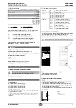
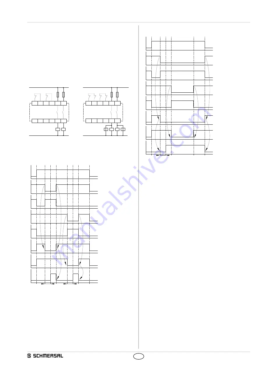
8.3 Actuator configuration
Single-channel control with feedback circuit (Fig. 10)
• Suitable for increase in capacity or number of contacts by
means of contactors or relays with positive-guided contacts.
•
S
= feedback circuit: If the feedback circuit is not required,
establish a bridge.
Dual-channel control with feedback circuit (Fig. 11)
• Suitable for increase in capacity or number of contacts by
means of contactors or relays with positive-guided contacts.
•
S
= feedback circuit: If the feedback circuit is not required,
establish a bridge.
X1
X3 X4
X2
33
13
34
14
K
B
K
A
S
L1
N
K
A
K
B
S
X1
X3 X4
X2
33
13
34
14
K
C
K
D
K
B
K
A
S
L1
N
K
B
K
A
K
D
K
C
S
Fig. 10
Fig. 11
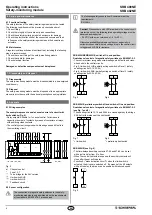
8.4 Flowcharts
Flowchart SRB 400NE / SRB 402NE (Fig. 12)
*
*
a)
b)
c)
d)
e)
f)
g)
h)
Fig. 12
a) Operating voltage UB;
b) Limit switch RHS (S12-S22);
c) Feedback circuit X1-X2;
d) Limit switch LHS (S32-S42);
e) Feedback circuit X3-X4;
f) Enabling circuit 13-14 / 23-24;
g) Enabling circuit 33-34 / 43-44;
h) Auxiliary contact 57-58 / 67-68;
* = pull-in delay
Flowchart SRB 402NE, preliminary limit switch and limit switch
(Fig. 13)
*
a)
b)
c)
d)
e)
f)
g)
h)
Fig. 13
a) Operating voltage U
B
;
b) Preliminary limit switch S32-S42;
c) Feedback circuit X3-X4;
d) Limit switch S12-S22;
e) Feedback circuit X1-X2;
f) Enabling circuit 33-34 / 43-44;
g) Enabling circuit 13-14 / 23-24;
h) Auxiliary contact 57-58 / 67-68;
* = pull-in delay

