background image

14

Operating instructions

Safety-monitoring module

SRB-E-232ST

EN

1.4  Appropriate use

The products described in these operating instructions are developed to 

execute safety-related functions as part of an entire plant or machine. It 

is the responsibility of the manufacturer of a machine or plant to ensure 

the correct functionality of the entire machine or plant.

The safety-monitoring module must be exclusively used in accordance 

with the versions listed below or for the applications authorised by the 

manufacturer. Detailed information regarding the range of applications 

can be found in the chapter "Product description".

1.5  General safety instructions

The user must observe the safety instructions in this operating 

instructions manual, the country-specific installation standards as well 

as all prevailing safety regulations and accident prevention rules.

Further technical information can be found in the Schmersal 

catalogues or in the online catalogue on the Internet:  

www.schmersal.net.

The information contained in this operating instructions manual is 

provided without liability and is subject to technical modifications.

The entire concept of the control system, in which the safety 

component is integrated, must be validated to the relevant 

standards.

There are no residual risks, provided that the safety instructions as well 

as the instructions regarding mounting, commissioning, operation and 

maintenance are observed.

1.6  Warning about misuse

In case of inadequate or improper use or manipulations of  

the safety-monitoring module, personal hazards or damage  

to machinery or plant components cannot be excluded. 

The relevant requirements of the standards ISO 14119 and 

ISO 13850 must be observed.

1.7  Exclusion of liability

We shall accept no liability for damages and malfunctions resulting from 

defective mounting or failure to comply with this operating instructions 

manual. The manufacturer shall accept no liability for damages 

resulting from the use of unauthorised spare parts or accessories.

For safety reasons, invasive work on the device as well as arbitrary 

repairs, conversions and modifications to the device are strictly 

forbidden; the manufacturer shall accept no liability for damages 

resulting from such invasive work, arbitrary repairs, conversions and/or 

modifications to the device.

The safety relay module is to be operated in an area in which access by 

personnel is restricted.

2.  Product description

2.1  Ordering code

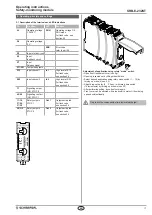
This operating instructions manual applies to the following types:

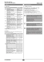
SRB-E-232ST-

No. Option

Description

Plug-in screw clamps: single wire (rigid)  

or fine wire (flexible): 0.2 … 2.5 mm²;  

fine wire with ferrule: 0.25 … 2.5 mm²

CC

Plug-in cage clamps: single wire (rigid)  

or fine wire (flexible): 0.2 … 1.5 mm²;  

fine wire with ferrule: 0.25 … 1.5 mm²

Only if the action described in these operating instructions is 

carried out correctly will the safety function be safeguarded, 

including compliance with the Machinery Directive.

2.2  Special versions

For special versions, which are not listed in the order code below 2.1, 

these specifications apply accordingly, provided that they correspond to 

the standard version.

2.3  Destination and use

The safety-monitoring modules for integration in safety circuits are 

designed for fitting in control cabinets. They are used for the safe 

evaluation of the signals of positive break position switches or safety 

sensors for safety functions on sliding, hinged and removable safety 

guards as well as emergency stop control devices, safety solenoid 

switches and AOPD's.

The safety function is defined as deactivating outputs Q1, Q2 and 

17-18, 27-28, 37-38 when inputs S12 and/or S22 are opened. Taking 

account of a PFH value assessment, the safety-relevant current 

paths meet the following requirements (see also chapter 2.6 “Safety 

classification”):

– Control category 4 - PL e to ISO 13849-1  

– SIL 3 to IEC 61508  

– SILCL 3 to IEC 62061

To determine the Performance Level (PL) to ISO 13849-1 of the entire 

safety function (e.g. sensor, logic, actuator), an assessment of all 

relevant components is required.

Summary of Contents for SRB-E-232ST

Page 1: ...e Montagehinweise 4 3 2 Abmessungen 4 4 Elektrischer Anschluss 4 1 Allgemeine Hinweise zum elektrischen Anschluss 4 4 2 Kodierung der Anschlussklemmen 4 5 Wirkungsweise und Einstellungen 5 1 Klemmenbeschreibung und LED Anzeigen 5 5 2 Einstellbare Anwendungen 6 5 3 Ändern der Einstellung bzw Anwendung 6 6 Diagnose 6 1 LED Anzeigen 7 6 2 Störungen 7 7 Anschlussbeispiele 7 1 Mögliche Anwendungen 7 7 ...

Page 2: ...eren ist jede weitere Haftung des Herstellers ausgeschlossen Jegliche eigenmächtige Reparaturen Umbauten und Veränderungen sind aus Sicherheitsgründen nicht gestattet und schließen eine Haftung des Herstellers für daraus resultierende Schäden aus Der Sicherheits Relais Baustein ist in einem für das Personal einge schränkten Bereich zu betreiben 2 Produktbeschreibung 2 1 Typschlüssel Diese Betriebs...

Page 3: ...sicherung 10 A flink 6 A träge Gebrauchskategorie nach IEC 60947 5 1 AC 15 230 V 4 A DC 13 24 V 4 A Schaltvermögen der Hilfskontakte 45 46 24 VDC 1 A Absicherung des Hilfskontakte Schmelzsicherung 2 5 A flink 2 A träge Kennwerte Sicherheitskontakte Widerstand max 100 mΩ AgNi selbstreinigend zwangsgeführt Elektrische Lebensdauer siehe 2 5 Mechanische Lebensdauer 10 Millionen Schaltspiele Halbleiter...

Page 4: ...e Abweichende Anwendungen auf Anfrage Kontaktlast nop y tcycle 20 880 000 0 6 min 40 330 000 1 6 min 60 110 000 5 0 min 80 44 000 12 0 min 100 17 600 30 0 min 3 Montage 3 1 Allgemeine Montagehinweise Die Befestigung erfolgt via Schnellbefestigung für Normschienen gemäß EN 60715 Das Gehäuse mit der Oberseite in die Hutschiene einhängen und nach unten drücken bis es einrastet 3 2 Abmessungen Alle Ma...

Page 5: ...nge aktiviert Blinkcode siehe Abs 5 4 Q1 Q2 Sicherheits ausgänge Stopp 0 Out 2 Ausgänge aktiviert Blinkcode siehe Abs 5 4 1 0 S11 S12 S21 S22 A1 A2 X3 X2 Q2 Q1 X7 Y1 SRB E 23 2ST 28 27 18 17 46 45 38 37 time s RUN ERR ln 1 ln 2 Out 1 Out 2 mode Einstellung der Anwendung mit dem Drehschalter mode Öffnen der transparenten Frontabdeckung siehe Abb Das Öffnen erfolgt durch das Anheben an der Verschlus...

Page 6: ...alter mode Drehschalter time Systemverhalten LED Anzeigen RUN In 1 In 2 Out Werkseinstellung Position 1 0 s Betriebsbereit für Anwendung 1 Betriebsspannung anlegen Position 1 Ohne angeschlossene Sensorik Leuchtet Auf Position C drehen Anwendung 1 wird gelöscht Leuchtet Blinkt Blinkt Blinkt Einstellzyklus aktiv Anwendung 1 ist gelöscht Keine gültige Anwenung gespeichert Blinkt SRB E bereit für neue...

Page 7: ...Eingang S12 geschlossen Leuchtet permanent Zeitfenster für Synchronität überschritten Blinkt schnell Zweiter Kanal Eingang S22 hat nicht geöffnet Blinkt langsam In 2 Eingang S22 geschlossen Leuchtet permanent Zeitfenster für Synchronität überschritten Blinkt schnell Zweiter Kanal Eingang S12 hat nicht geöffnet Blinkt langsam Out 1 Sicherheitsausgang Stopp 1 EIN Leuchtet permanent Kein Freigabesign...

Page 8: ...Signalling outputs d Clock outputs e Processing f Power 7 2 Applikationsbeispiel Zweikanalige Ansteuerung dargestellt am Beispiel einer Schutztürüberwachung mit zwei Positionsschaltern davon ein Kontakt zwangsöffnend mit externem Reset Taster J Leistungsebene Zweikanalige Ansteuerung geeignet zur Kontaktverstärkung bzw Kontaktvervielfältigung durch Schütze oder Relais mit zwangsgeführten Kontakten...

Page 9: ...eset Taster ohne Flanken überwachung Autostart Drehschalter Position 1 Drehschalter Position 6 Drehschalter Position 2 Drehschalter Position 7 Drehschalter Position 3 Drehschalter Position 8 Drehschalter Position 4 Drehschalter Position 9 Drehschalter Position 5 Drehschalter Position 10 7 4 Rückführkreis Freigabesignal Geeignet zur Kontaktverstärkung bzw Kontaktvervielfältigung durch Relais bzw Sc...

Page 10: ...riebnahme Der Sicherheitsrelaisbaustein ist zur Montage in einem Schaltschrank mit der Schutzart IP54 vorgesehen Der Sicherheitsrelaisbaustein ist bei Anlieferung betriebsbereit Werkseitig ist bereits die Anwendung 1 voreingestellt 8 2 Funktionsprüfung Der Sicherheitsrelaisbaustein ist hinsichtlich seiner Sicherheitsfunktion zu testen Hierbei ist vorab Folgendes zu gewährleisten 1 Fester Sitz 2 Un...

Page 11: ...ind auszutauschen 9 Demontage und Entsorgung 9 1 Demontage Der Sicherheitsrelaisbaustein ist nur in spannungslosem Zustand zu demontieren 9 2 Entsorgung Der Sicherheitsrelaisbaustein ist entsprechend der nationalen Vorschriften und Gesetze fachgerecht zu entsorgen 10 Anhang 10 1 Schaltungshinweise Verdrahtungsbeispiel zur Kaskadierung über sicheren Eingang X7 Über den Eingang X7 können Sicherheits...

Page 12: ...l com Hiermit erklären wir dass die nachfolgend aufgeführten Bauteile aufgrund der Konzipierung und Bauart den Anforderungen der unten angeführten Europäischen Richtlinien entsprechen Bezeichnung des Bauteils SRB E 232ST Typ siehe Typenschlüssel Beschreibung des Bauteils Relais Sicherheitskombination für NOT HALT Schaltungen Schutztürüberwachungen Sicherheitsmagnetschalter und AOPD s Einschlägige ...

Page 13: ...6 Safety classification 16 3 Mounting 3 1 General mounting instructions 16 3 2 Dimensions 16 4 Electrical connection 4 1 General information for electrical connection 16 4 2 Coding of connecting terminals 16 5 Operating principle and settings 5 1 Description of the terminals and LED indications 17 5 2 Adjustable applications 18 5 3 Changing setting or application 18 6 Diagnostic 6 1 LED indication...

Page 14: ...cept no liability for damages resulting from the use of unauthorised spare parts or accessories For safety reasons invasive work on the device as well as arbitrary repairs conversions and modifications to the device are strictly forbidden the manufacturer shall accept no liability for damages resulting from such invasive work arbitrary repairs conversions and or modifications to the device The saf...

Page 15: ...tilisation category to IEC 60947 5 1 AC 15 230 V 4 A DC 13 24 V 4 A Switching capacity of the auxiliary contacts 45 46 24 VDC 1 A Fuse rating for the auxiliary contact safety fuse 2 5 A quick blow 2 A slow blow Safety contact values resistance max 100 mΩ AgNi self cleaning positive action Electrical life refer to 2 5 Mechanical life 10 million operations Semi conductor outputs Switching capacity o...

Page 16: ...the relay contacts Diverging applications upon request Contact load nop y tcycle 20 880 000 0 6 min 40 330 000 1 6 min 60 110 000 5 0 min 80 44 000 12 0 min 100 17 600 30 0 min 3 Mounting 3 1 General mounting instructions Mounting snaps onto standard DIN rails to EN 60715 Hook bottom of enclosure in DIN rail and push down until it engages in position 3 2 Dimensions All measurements in mm Device di...

Page 17: ...ntact NC STOP 1 17 18 27 28 37 38 Safety outputs STOP 1 Out 1 Outputs activated For flash code see section 5 4 Q1 Q2 Safety outputs STOP 0 Out 2 Outputs activated For flash code see section 5 4 1 0 S11 S12 S21 S22 A1 A2 X3 X2 Q2 Q1 X7 Y1 SRB E 23 2ST 28 27 18 17 46 45 38 37 time s RUN ERR ln 1 ln 2 Out 1 Out 2 mode Adjustment of application using rotary mode switch Open front transparent cover see...

Page 18: ...ry mode switch Rotary time switch System response LED indications RUN In 1 In 2 Out Factory setting Position 1 0 s Ready for application 1 Switch operating voltage on Position 1 Without connected sensors Lights up Turn to position C Application 1 is deleted Lights up Flashes Flashes Flashes Setting cycle active Application 1 is deleted No valid application stored Flashes SRB E ready for new applic...

Page 19: ...tinuously lit Not a valid application Flashes In 1 Input S12 closed Continuously lit Time window for synchronicity exceeded Flashes quickly Second channel input S22 has not opened Flashes slowly In 2 Input S22 closed Continuously lit Time window for synchronicity exceeded Flashes quickly Second channel input S12 has not opened Flashes slowly Out 1 Safety output STOP 1 ON Continuously lit No releas...

Page 20: ...outputs c Signalling outputs d Clock outputs e Processing f Power 7 2 Application example Dual channel control shown for a guard door monitor with two position switches where one has a positive break contact with external reset button J Relay outputs Suitable for 2 channel control for increase in capacity or number of contacts by means of contactors or relays with positive guided contacts Kontakte...

Page 21: ...2 J S11 S21 X2 24VDC J Reset button detection of the trailing edge Reset without monitoring autostart Rotary knob position 1 Rotary knob position 6 Rotary knob position 2 Rotary knob position 7 Rotary knob position 3 Rotary knob position 8 Rotary knob position 4 Rotary knob position 9 Rotary knob position 5 Rotary knob position 10 7 4 Feedback circuit Release signal Suitable for increase in capaci...

Page 22: ...ostart 8 Set up and maintenance 8 1 Commissioning The safety relay module features protection class IP54 for installation in a switch cabinet The safety relay module is delivered ready for operation Application 1 is preset in the factory 8 2 Functional testing The safety function of the safety monitoring module must be tested The following conditions must be previously checked and met 1 Correct fi...

Page 23: ... be replaced 9 Disassembly and disposal 9 1 Disassembly The safety monitoring module must be disassembled in a de energised condition only 9 2 Disposal The safety monitoring module must be disposed of in an appropriate manner in accordance with the national prescriptions and legislations 10 Appendix 10 1 Wiring circuit information Wiring example for cascading via safety input X7 Safety outputs of ...

Page 24: ...ernet www schmersal com We hereby certify that the hereafter described components both in their basic design and construction conform to the applicable European Directives Name of the component SRB E 232ST Type See ordering code Description of the component Relay safety combination for emergency stop circuits guard door monitoring solenoid safety switches and AOPDs Relevant Directives Machinery Di...

Reviews: