23
SRB-E-232ST
Operating instructions
Safety-monitoring module
EN
8.4 Setting report
This report regarding the setting of the device must be completed
accordingly by the customer and enclosed in the technical
documentation of the machine.
The setting report must be available whenever a safety check is
performed.
Company:
The safety-monitoring module is used in the following machine:
Machine n°
Machine type
Module n°
Configured application (mode):
Set drop-out delay (t):
Set on (date)
Signature of the responsible person
8.5 Maintenance
A regular visual inspection and functional test, including the following
steps, is recommended:
1. Check the correct fixing of the safety-monitoring module
2. Check the cable for damages
3. Check electrical function
If a manual functional check is necessary to detect a
possible accumulation of faults, then this must take place
during the intervals noted as follows:
• at least every month for PL e with category 3 or
category 4 (according to ISO 13849-1) or SIL 3 with HFT
(hardware fault tolerance) = 1 (according to IEC 62061);
• at least every 12 months for PL d with category 3
(according to ISO 13849-1) or SIL 2 with HFT (hardware
fault tolerance) = 1 (according to IEC 62061).
Damaged or defective components must be replaced.
9. Disassembly and disposal
9.1 Disassembly
The safety-monitoring module must be disassembled in a de-energised
condition only.
9.2 Disposal
The safety-monitoring module must be disposed of in an appropriate
manner in accordance with the national prescriptions and legislations.
10.
Appendix
10.1
Wiring/circuit information
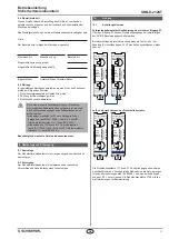
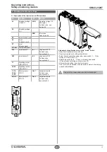
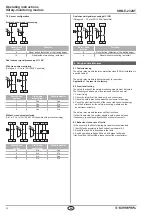
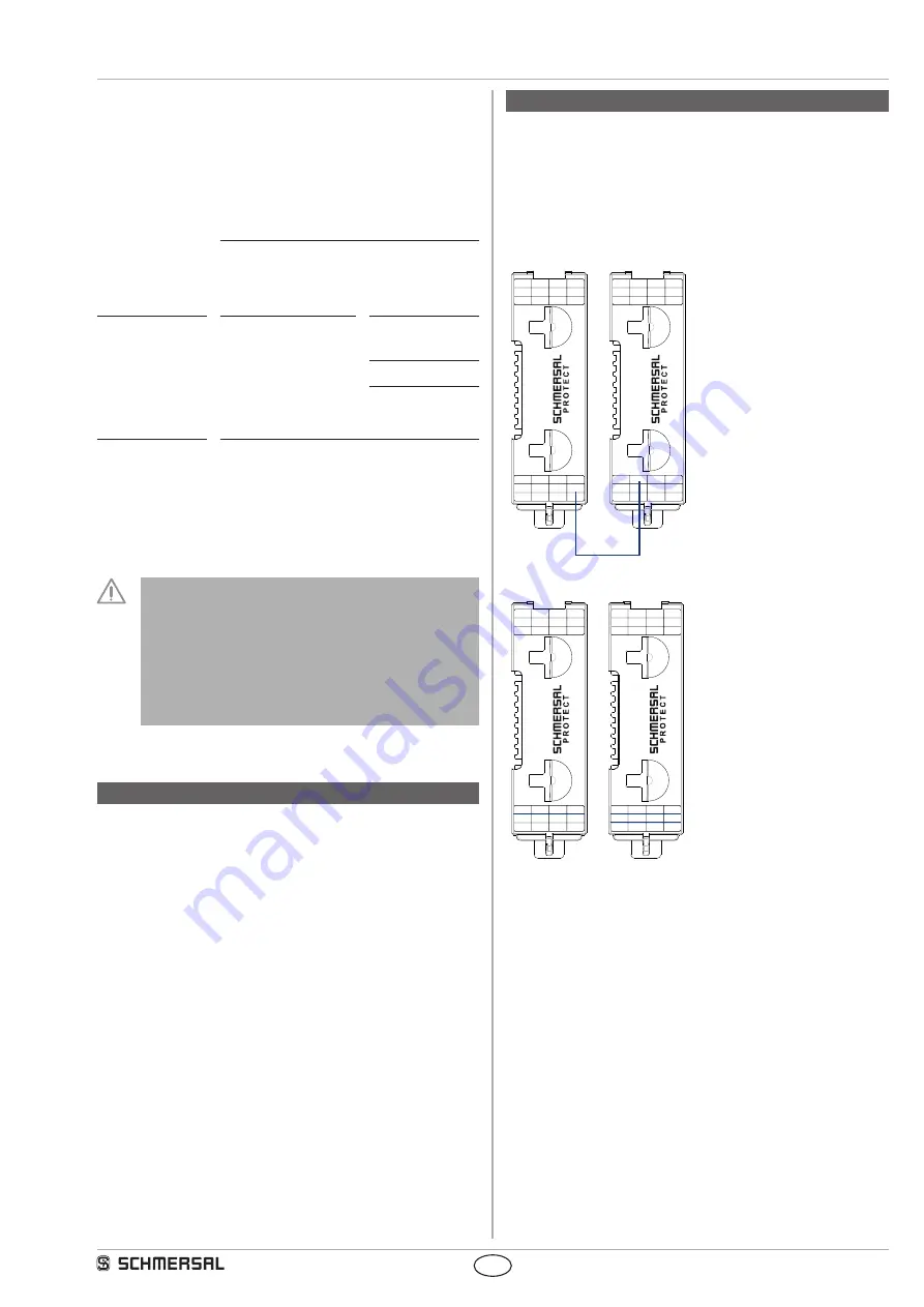
Wiring example for cascading via safety input X7:
Safety outputs of following SRB-E modules can be switched off in
each case via input X7.
For safety-orientated application, a fault in the wiring (short circuit to
24 V potential) must be able to be excluded!
1
0
S11 S12 S21 S22
A1
A2
X3
X2
X7
Qt1
Y2
Y1
S
R
B
-E
-2
12
ST
24
23
14
13
Out 2
time[s]
RUN
ERR
ln 1
ln 2
Out 1
mode
1
0
S11 S12 S21 S22
A1
A2
X3
X2
Q2
Q1
X7
Y1
S
R
B
-E
-2
3 2
ST
28
27
18
17
46
45
38
37
time[s]
RUN
ERR
ln 1
ln 2
Out 1
Out 2
mode
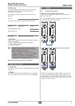
Air clearances and creepage distances of the safety contacts:
1
0
S11 S12 S21 S22
A1
A2
X3
X2
X7
Qt1
Y2
Y1
S
R
B
-E
-2
12
ST
24
23
14
13
Out 2
time[s]
RUN
ERR
ln 1
ln 2
Out 1
mode
1
0
S11 S12 S21 S22
A1
A2
X3
X2
Q2
Q1
X7
Y1
S
R
B
-E
-2
3 2
ST
28
27
18
17
46
45
38
37
time[s]
RUN
ERR
ln 1
ln 2
Out 1
Out 2
mode
Against all other connection terminals, the safety contacts 17-18 and
27-28 comply without additional measures with the requirements for
double insulation in accordance with IEC 60664-1 and are to be used
with switch voltages > 50 V. The safety contacts 37-38 comply with the
requirements for basic insulation.

