3
SRB-E-301MC
Operating instructions
Safety-monitoring module
EN
Electrical characteristics:
Rated operating voltage U
e
:
24 VDC –15% / +20%,
residual ripple max. 10%
24 VAC –15% / +10%
Frequency range:
50 Hz/60 Hz
Power consumption:
3.4 W, 8.5 VA
Fuse rating for the operating voltage:
internal fuse,
tripping current > 1A
Insulation values in accordance with IEC 60664-1:
Rated insulation voltage U
i
:
- Safety contacts:
250 V
Rated impulse withstand voltage U
imp
:
- Safety contacts 13-14, 23-24, 33-34:
4 kV
Overvoltage category:
III
Degree of pollution:
2
Pull-in delay:
< 120 ms
Drop-out delay in case of "emergency stop":
< 10 ms
Drop-out delay on "supply failure":
< 50 ms
Bridging in case of voltage drops:
typ. 40 ms
Control current circuits/inputs:
Inputs S12, S22:
24 VDC/10 mA
Inputs X2:
24 VDC/10 mA
Cable length:
1500 m with 1.5 mm²;
2500 m with 2.5 mm²
Conduction resistance:
max. 40 Ω
Relay outputs:
Switching capacity of the safety contacts:
13-14, 23-24, 33-34:
max. 250 VDC, 6 A ohmic,
min. 10 VDC / 10 mA
(Derating see 2.5)
Fuse rating of the safety contacts:
external (I
k
= 1000 A)
to IEC 60947-5-1
Safety fuse 10 A quick blow, 6 A slow blow
Utilisation category to IEC 60947-5-1:
DC-13: 24 V / 4 A
AC-15: 230 V / 4 A
Switching capacity of the auxiliary contacts:
41-42: 24 VDC / 1 A
Fuse rating for the auxiliary contact:
safety fuse
1.5 A quick blow, 1 A slow blow
Electrical life:
refer to 2.5
Mechanical life:
10 million operations
S
afety contact values:
resistance max. 100 mΩ, AgNi,
self-cleaning, positive action
Max. switching cycles / minute:
20
Inductive consumers:
Provision should be made
for a suitable protection circuit.
Mechanical data:
Connection type:
refer to 2.1
Cable section:
refer to 2.1
Connecting cable:
rigid or flexible
Tightening torque for the terminals:
0.5 Nm
Material of enclosure:
glass-fibre reinforced thermoplastic, ventilated
Weight:
175 g
Ambient conditions:
Ambient temperature:
–25°C … +60°C
(non condensing)
Storage and transport temperature:
–40°C … +85°C
(non condensing)
Protection class:
Enclosure: IP40,
Terminals: IP20,
Clearance: IP54
Resistance to shock:
30 g / 11 ms
Resistance to vibrations
to IEC 60068-2-6:
10 ... 55 Hz, amplitude 0.35 mm
Altitude:
max. 2,000 m
The data specified in this manual apply for operation of equipment with
rated operating voltage U
e
±0%.
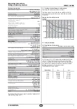
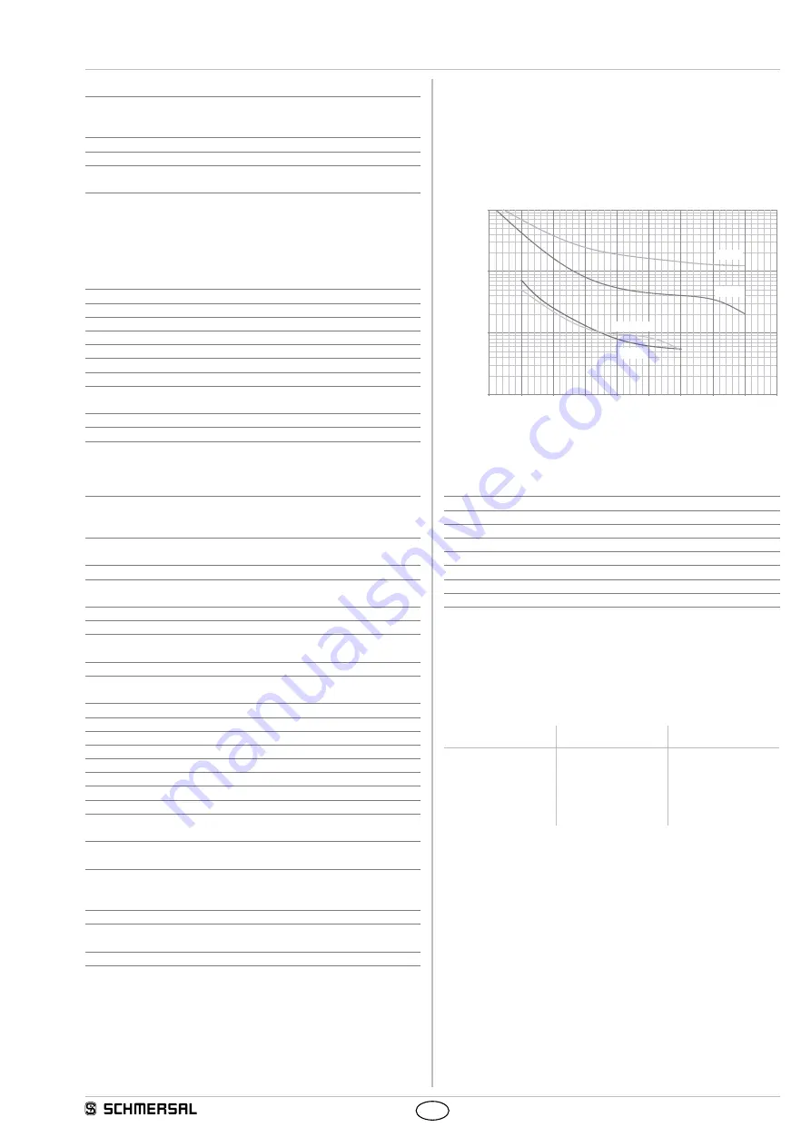
2.5 Derating / electrical lifespan of safety contacts
No derating with individual installation of modules.
Derating on request if several modules are installed one after the
other without spacing and with maximum output load and ambient
temperatures.
Electrical life of the safety contacts
DC13 24V
AC15 230V
AC1 230V
DC1 24V
10.000.000
1.000.000
100.000
10.000
0 1 2 3 4 5 6 7 8 9
Operations
Contact load in amperes
2.6 Safety classification
2.6.1 Classification of relay output
Standards:
ISO 13849-1, IEC 61508, IEC 62061
PL:
e
Control Category:
4
DC:
high
CCF:
> 65 points
PFH
D
:
≤ 6.0 x 10
-9
/ h
PFD
avg
:
≤ 4.0 x 10
-4
SIL:
suitable for SIL 3 applications
Service life:
20 years
The PFH value of 6.0 × 10
-9
/h applies to the combinations of contact
load (current through enabling contacts) and number of switching
cycles (n
op/y
) mentioned in the table below. At 365 operating days per
year and a 24-hours operation, this results in the below-mentioned
switching cycle times (t
cycle
) for the relay contacts.
Diverging applications upon request.
Contact load
n
op/y
t
cycle
20 %
880,000
0.6 min
40 %
330,000
1.6 min
60 %
110,000
5.0 min
80 %
44,000
12.0 min
100 %
17,600
30.0 min


