3
SRB NA-R-C.33
Operating instructions
Safety-monitoring module
EN
2.5
Safety classification
Standards:
EN ISO 13849-1, IEC 61508,
EN 60947-5-1
PL:
Stop 0: up to e
Control category:
Stop 0: up to 4
DC:
Stop 0: 99% (high)
CCF:
> 65 points
SIL:
Stop 0: up to 3
Service life:
20 years
B
10d
value (for one channel):
Low voltages range 20%: 20,000,000
40%: 7,500,000
60%: 2,500,000
80%: 1,000,000
Maximum load 100%: 400,000
MTTF
B
d x
x
h
s/h
3600
d
10d
op
op
op
n
0,1 x n
op
t
cycle
For an average annual demand rate of n
op
= 126,720 cycles per
year, Performance Level PL e can be obtained at maximum load.
n
op
= average number of activations per year
d
op
= average number of operating days per year
h
op
= average number of operating hours per day
t
cycle
= average demand rate of the safety function in s
(e.g. 4 × per hour = 1 × per 15 min. = 900 s)
(Specifications can vary depending on the application-specific
parameters h
op
, d
op
and t
cycle
as well as the load.)
3 Mounting
3.1 General mounting instructions
Mounting: snaps onto standard DIN rails to EN 60715.
Snap the bottom of the enclosure slightly tilted forwards in the
DIN rail and push up until it latches in position.
3.2 Dimensions
All measurements in mm.
Device dimensions (H/W/D): 83 x 45 x 140 mm
4 Electrical connection
4.1 General information for electrical connection
The electrical connection may only be carried out
by authorised personnel in a de-energised condition.
Wiring examples: see appendix
5 Operating principle and settings
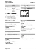
5.1 LED functions
•
K1: Status channel 1
•
K2: Status channel 2
• U
i
: Status internal operating voltage (LED is on, when the
operating voltage on the terminals A1-A2 is ON and the fuse
has not been triggered)
• U
B
: Status operating voltage (LED is on, when the operating
voltage on the terminals A1-A2 is ON)
Description of the terminals
Voltages:
A1
A2
+24 VDC
0 VDC
Inputs:
T11-T12
T11-T22
Input channel 1
Input channel 2
Outputs:
13-14
23-24
33-34
First safety enabling circuit
Second safety enabling circuit
Third safety enabling circuit
Start:
T33-T34
X1-X2
Reset
Feedback circuit
T33
41
42
T11
SRB-NA-R-C.33
34
T12
24
T12
T22
X2
K2
UB
K1
Ui
T34
a)
33
PE
23
X1
14
13
A2
A1
Fig. 1
a) Fuse
6 Set-up and maintenance
6.1 Functional testing
The safety function of the safety-monitoring module must be tested.
The following conditions must be previously checked and met:
1. Correct fixing
2. Check the integrity of the cable entry and connections
3. Check the safety-monitoring module’s enclosure for damage.
4. Check the electrical function of the connected sensors and
their influence on the safety-monitoring module and the
downstream actuators
6.2 Maintenance
A regular visual inspection and functional test, including the following
steps, is recommended:
1. Check the correct fixing of the safety-monitoring module
2. Check the cable for damages
3. Check electrical function
Damaged or defective components must be replaced.
7 Disassembly and disposal
7.1 Disassembly
The safety-monitoring module must be disassembled in a de-energised
condition only.
7.2 Disposal
The safety-monitoring module must be disposed of in an appropriate
manner in accordance with the national prescriptions and legislations.


