4
Operating instructions
Safety-monitoring module
SRB NA-R-C.33
EN
8.3
Sensor configuration
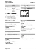
Single-channel emergency stop circuit with command devices
to DIN EN ISO 13850 (EN 418) and EN 60947-5-5 (Fig. 4)
•
Wire breakage and earth leakage in the control circuits are detected.
•
Possible control categories:
– 1 to EN 954-1
– 2 – PL d to DIN EN ISO 13849-1
Dual-channel emergency stop circuit with command devices
to DIN EN ISO 13850 (EN 418) and EN 60947-5-5 (Fig. 5)
•
Wire breakage and earth leakage in the control circuits are detected.
•
Cross-wire shorts between the control circuits are detected.
•
Possible control categories:
– 4 to EN 954-1
– 4 – PL e to DIN EN ISO 13849-1
T12 T22
T12
T11
X2
X1
T12
T11
T22
T11
X2
X1
Fig. 4
Fig. 5
Single-channel guard door monitoring circuit with interlocking
devices to EN 1088 (Fig. 6)
•
At least one contact with positive break required
•
Wire breakage and earth leakage in the control circuits are detected.
•
Possible control categories:
– 1 to EN 954-1
– 2 – PL d to DIN EN ISO 13849-1
Dual-channel guard door monitoring circuit with interlocking
device to EN 1088 (Fig. 7)
•
At least one contact with positive break required
•
Wire breakage and earth leakage in the control circuits are detected.
•
Cross-wire shorts between the control circuits are detected.
•
Possible control categories:
– 4 to EN 954-1
– 4 – PL e to DIN EN ISO 13849-1
T12 T22
T12
T11
X2
X1
T12
T11
T22
T11
X2
X1
Fig. 6
Fig. 7
8 Appendix
8.1 Wiring examples
Dual-channel control, shown for a guard door monitor with two
position switches where one has a positive break contact; with
external reset button
J
(Fig. 3)
•
Relay outputs: Suitable for 2-channel control, for increase in capacity
or number of contacts by means of contactors or relays with positive-
guided contacts.
•
The control system recognises wire-breakage and earth faults in the
monitoring circuit.
•
Cat. 3 bzw. 4
•
For an AC operating voltage, a detachable connection between the
device and the functional earth is required to DIN VDE 0110 Part 725.
K1
F1
F2
A1 T11
X1
X2
T34
L1
N
K
A
K
A
K1
K2
A2
42
41
33
23
51
K
A
K
B
J
S
34
24
14
T12 T12 T22
13
K
B
K
B
PE
a)
K2
K1
K2
T33
Fig. 2
S
= Feedback circuit
a) Logic
8.2
Start configuration
External reset button (non-monitored start) (see Fig. 3)
•
The external reset button is integrated in the feedback circuit in series.
•
The safety-monitoring module is activated upon actuation of the reset
button.
J
T34
T33
Fig. 3


