4
Operating instructions
Safety-monitoring module
SRB NA-R-C.39/ST2
EN
8.3
Sensor configuration
Single-channel guard door monitoring circuit with interlocking
devices to EN 1088 (Fig. 5)
• At least one contact with positive break required
•
Wire breakage and earth leakage in the control circuits are detected.
• Possible control categories:
– 1 to EN 954-1
– 2 – PL d to DIN EN ISO 13849-1
•
Caution:
Automatic activation of the safety enabling paths after the
safety guard is closed.
Dual-channel guard door monitoring circuit with interlocking
device to EN 1088 (Fig. 6)
• At least one contact with positive break required
•
Wire breakage and earth leakage in the control circuits are detected.
•
Cross-wire shorts between the monitoring circuits are not detected.
• Possible control categories:
– 3 to EN 954-1
– 4 to EN 954-1 (with protective wiring)
– 4 – PL e to DIN EN ISO 13849-1 (with protective wiring)
•
Caution:
Automatic activation of the safety enabling paths after the
safety guard is closed.
T12
T11
T22
T12
T34
T33
T12
T11
T22
T11
T34
T33
Fig. 5
Fig. 6
8.4
Actuator configuration
Single-channel control with feedback circuit (Fig. 7)
•
Suitable for increase in capacity or number of contacts by means of
contactors or relays with positive-guided contacts.
• If the feedback circuit is not required, establish a bridge.
•
S
= Feedback circuit:
if the feedback circuit is not required, establish a bridge.
Dual-channel control with feedback circuit (Fig. 8)
•
Suitable for increase in capacity or number of contacts by means of
contactors or relays with positive-guided contacts.
•
S
= Feedback circuit:
if the feedback circuit is not required, establish a bridge.
X1 X2 13
14
K
A
S
L1
N
K
A
X1 X2
13
14
K
A
S
L1
N
K
B
K
A
K
B
Fig. 7
Fig. 8
7 Disassembly and disposal
7.1 Disassembly
The safety-monitoring module must be disassembled in a de-energised
condition only.
7.2 Disposal
The safety-monitoring module must be disposed of in an appropriate
manner in accordance with the national prescriptions and legislations.
8 Appendix
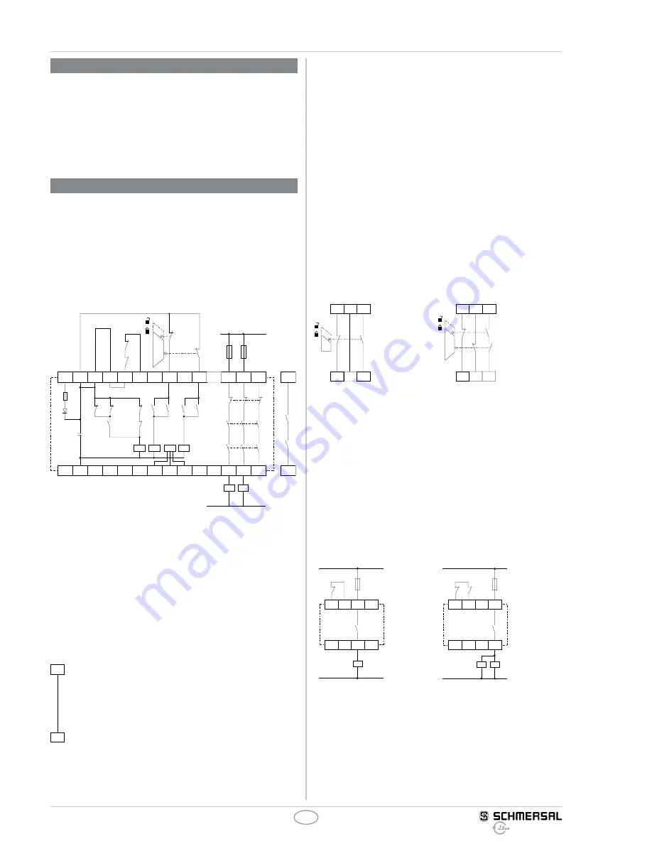
8.1 Wiring examples
Dual-channel control, shown for a guard door monitor with two
position switches where one has a positive break contact;
with external reset button
J
(Fig. 3)
• Relay outputs: Suitable for 2-channel control, for increase in capacity
or number of contacts by means of contactors or relays with positive-
guided contacts.
•
The control system recognises wire-breakage and earth faults in the
monitoring circuit.
K1
K2
K3
F1
K2
K1
K2
K3
A1 T11 T33 T34 X1
L1
K
A
K2
K3
K1
33
23
K
A
K
B
T22
13
K
B
X2
T12
K1
K3
N
K
A
34
24
14
K
B
L14 L13
D2
A2
K3
K2
K1
Fig. 3
8.2
Start configuration
Automatic start (see Fig. 4)
•
The automatic start is programmed by connecting the feedback circuit
to the terminals T33-T34.
•
Caution:
Not admitted without additional measures due to the risk of
gaining access by stepping behind!
• within the meaning of EN 60204-1:2006 paragraph 9.2.5.4.2 and
10.8.3, the operating mode "automatic start" is only restrictedly
admissible. In particular, any inadvertent restart of the machine
must be prevented by other suitable measures.
T34
T33
Fig. 4


