5
TZM/TZF SPEZ
Operating instructions
Solenoid interlock
EN
Components with LED indication only for 24VDC. The
monitoring contacts of the LED versions are not potential-
free. In combination with these devices, only sequential
circuits can be used, in which both channels are controlled
with positive potential.
For the cable entry, suitable cable glands with an appropriate degree of
protection must be used.
After wiring, the wiring compartment must be cleaned (i.e. remove
excess cables etc.). The fixing screws of the wiring compartment cover
must be tightened with 0.8 Nm tightening torque.
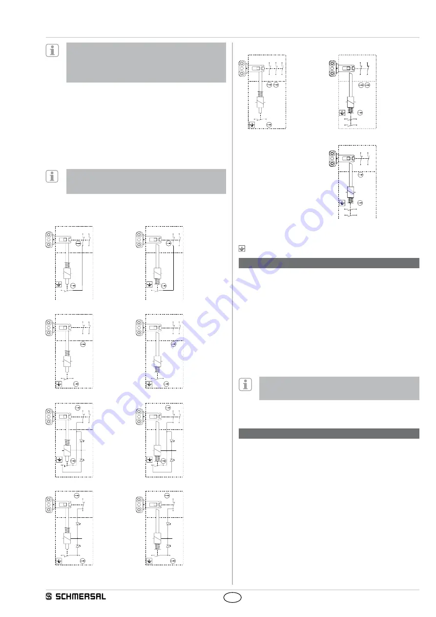
4.2 Contact variants
Contact variants are shown in a de-energised condition with
actuator inserted.
LED display:
1) Safety guard closed
2) Safety guard closed and locked
Power to unlock
Power to lock
TZF…
TZM…
21
E2
E1
11
12
33
34
22
21
22
E2
E1
11
33
34
12
TZFW…
TZMW…
21
22
E2
E1
11 33
12 34
21
22
E2
E1
11 33
12 34
TZFL
TZML
21
11 33
E2
gn
2
ye
1
22
E1
12 34
21
11 33
E2
gn
2
ye
1
22
E1
12 34
TZFWL
TZMWL
21
22
E1
E2
11
ye
1
gn
2
12
21
22
gn
2
ye
1
E2
E1
11
12
TZFW…3NC
TZMW4Ö
Power to unlock
Power to lock
21
22
E2
E1
41 33
11
12 42 34
21
22
E2
E1
11
12 42
41
32
31
TZMW...2MOE
21
22
E2
E1
42
41
33
11
12 34
Key
A
positive break NC contact
Monitoring the interlock according to ISO 14119
5. Set-up and maintenance
5.1 Functional testing
The safety function of the safety components must be tested.
The following conditions must be previously checked and met:
1. Fitting of the solenoid interlock and the actuator.
2. Check the integrity of the cable entry and connections.
3. Check the switch enclosure for damage.
5.2 Maintenance
A regular visual inspection and functional test, including the following
steps, is recommended:
1. Check for tight installation of the actuator and the switch.
2. Remove particles of dust and soiling.
3. Check cable entry and connections.
Adequate measures must be taken to ensure protection
against tampering either to prevent tampering of the safety
guard, for instance by means of replacement actuators.
Damaged or defective components must be replaced.
6. Disassembly and disposal
6.1 Disassembly
The safety switchgear must be disassembled in a de-energised
condition only.
6.2 Disposal
The safety switchgear must be disposed of in an appropriate manner in
accordance with the national prescriptions and legislations.


