background image

3

TZG

Operating instructions

Safety switch

EN

60

30

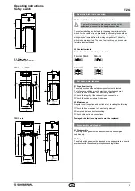
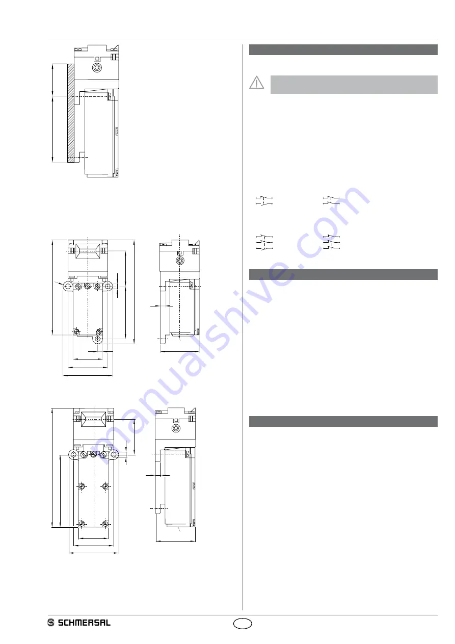
3.2  Dimensions

All measurements in mm

TZG 2-pole / TZGP

35

5

39,5

30

50

39,5

R5

96.5

10

5.3

106.5

55

M20 x 1,5

TZG 3-pole

5

39,5

30

50

39,5

122

75,5

35

5.3

M20 x 1,5

4.  Rear side Electrical connection

4.1  General information for electrical connection

The electrical connection may only be carried out by 

authorised personnel in a de-energised condition

The contact labelling can be found in the wiring compartment of the 

switch For the cable entry, only suitable plastic cable glands with an 

appropriate degree of protection must be used After wiring, dust and 

soiling must be removed from the wiring compartment The safety 

switch is double insulated The use of a protective ground connector 

therefore is not authorised

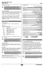
4.2  Contact variants

Contacts are shown with safety guard closed

TZG../103 / TZGP

TZG../110

11

23

12

24

11

21

12

22

TZG../1103

TZG../3330

11

21

33

12

22

34

11

21

31

12

22

32

5.  Set-up and maintenance

5.1  Functional testing

The safety function of the safety components must be tested  

The following conditions must be previously checked and met:

1 Check the free movement of the actuating element

2 Check the integrity of the cable entry and connections

3 Check the switch enclosure for damage

5.2  Maintenance

A regular visual inspection and functional test, including the following 

steps, is recommended:

1 Check the free movement of the actuating element

2 Remove particles of dust and soiling

3 Check cable entry and connections

Damaged or defective components must be replaced.

6.  Disassembly and disposal

6.1  Disassembly

The safety switchgear must be disassembled in a de-energised 

condition only

6.2  Disposal

The safety switchgear must be disposed of in an appropriate manner in 

accordance with the national prescriptions and legislations

Summary of Contents for TZG

Page 1: ... used in accordance with the versions listed below or for the applications authorised by the manufacturer Detailed information regarding the range of applications can be found in the chapter Product description 1 5 General safety instructions The user must observe the safety instructions in this operating instructions manual the country specific installation standards as well as all prevailing saf...

Page 2: ... the safety guard is opened When the safety guard is opened the NC contacts are positively opened and the NO contacts are closed The user must evaluate and design the safety chain in accordance with the relevant standards and on the required safety level 2 4 Technical data Standards IEC 60947 5 1 EN ISO 13849 1 ISO 14119 BG GS ET 15 Enclosure glass fibre reinforced thermoplastic self extinguishing...

Page 3: ...are shown with safety guard closed TZG 103 TZGP TZG 110 11 23 12 24 11 21 12 22 TZG 1103 TZG 3330 11 21 33 12 22 34 11 21 31 12 22 32 5 Set up and maintenance 5 1 Functional testing The safety function of the safety components must be tested The following conditions must be previously checked and met 1 Check the free movement of the actuating element 2 Check the integrity of the cable entry and co...

Page 4: ... TZG Type See ordering code Description of the component Positive break position switch with separate actuator for safety functions Relevant Directives Machinery Directive RoHS Directive 2006 42 EC 2011 65 EU Applied standards DIN EN 60947 5 1 2010 DIN EN ISO 14119 2014 Person authorised for the compilation of the technical documentation Oliver Wacker Möddinghofe 30 42279 Wuppertal The currently v...

Page 5: ...50 99 4 35 54 50 30 20 M 6 40 14 36 Rmin 650 Rmin 175 Flexible actuator TZ COF HIS 1 Flexible actuator TZ COF HIS 2 Flexible actuator TZ CORF HIS 1 Flexible actuator TZ CORF HIS 2 Ordering details Flexible actuator TZ COF HIS 1 Flexible actuator TZ COF HIS 2 Flexible actuator TZ CORF HIS 1 Flexible actuator TZ CORF HIS 2 System components 12 32 20 4 2 15 4 2 3 8 47 5 12 5 Rmin 250 Rmin 160 4 2 20 ...

Reviews: