EFA bung dropper Translation of the original operating instructions
EN
V 05.2021
15 of 27
3
2
1
Air outlet
Guide pin
Blade,
complete
Operating
lever
Handle
Handle area
Cold water valve
push button
Eyebolt for spring
balancer
Vacuum connection
Flushing water
connection
Air inlet
5.1.2
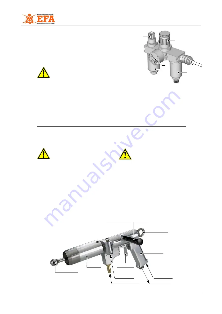
Oil mist lubricator
The bung dropper is operated with compressed air.
The connection must be made via an oil mist lubricator R 3/8”,
see Fig. 5.3
.
The supply line for the connection of a bung dropper must have a
minimum clear width of 13 mm.
Caution!
Tripping hazard!
We recommend that the lines are led
away upwards.
Lines that run along the floor can be a
tripping hazard for the worker!
To ensure lubrication of the pneumatic motor, the oil mist lubricator must be set to 2
– 3 drops of oil per
minute.
For proper functioning and to maintain the appropriate service life of the bung dropper, the oil mist lubricator
must be checked at regular intervals and the water separator must be emptied.
Check at regular intervals, min. 2x per month, remove the condensation and top up with special oil.
For complete information about the oil mist lubricator, read the operating instructions supplied with it.
5.1.3
Connecting the bung dropper
The bung dropper is supplied by the factory in a state that it is immediately ready for use.
Danger!
Observe the assembly
sequence!
Danger!
Do not leave a tool key in the
machine!
Representation,
see Appendix A1
– Installation diagram
Connect the bung dropper to an oil mist lubricator (accessories) with an air hose (accessories).
Mount the oil mist lubricator in the following order:
Water separator (1),
Pressure gauge (2) with
regulator (3),
Oiler (4) with dosing screw (5),
see Fig. 5.3 Oil mist lubricator
.
Setting while the device is running to:
P = 6 bar
and
2
– 3 drops of oil per minute.
Connect the bung dropper to the vacuum system (special accessories) using a vacuum hose
(accessories).
The bung dropper must be mounted on a spring balancer (special accessories) for safe working,
see Fig. 5.1.1 Spring balancer
.
Connect the vacuum system to the mains.
5.2
Machine overview
Fig. 5.4
– Machine components
4
Fig. 5.3
– Oil mist lubricator
5


