Acuity AP820 Laser
Scanners Rev. 3.3
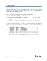
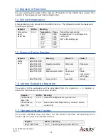
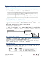
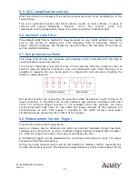
16
4.3
Power On
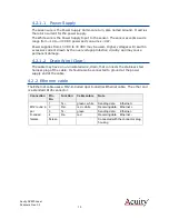
Caution: be sure that the laser will not cause an eye hazard.
When power is applied the red or blue laser line will be emitted from the top window
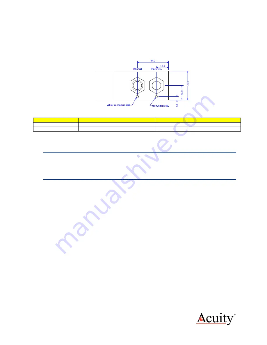
of the AP820 scanner. The LEDS adjacent to the cable connectors on the scanner head
should illuminate.
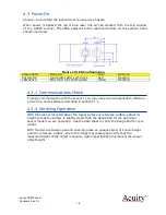
Figure 10 LED Configuration
Status LEDs
Meaning
Color
OK when
System OK
Illuminates after self-check
Red
Flashing
LAN active
Ethernet Link sending data
Yellow
Flashing
4.3.1
Communications Check
To begin communication with the scanner, you may use your own application software
or the free, demo software described in section
4.3.2
Verifying Operation
With the scanner mounted above the target surface or reference surface, adjust its
height so that the surface is slightly closer than the
Range End
for the particular
sensor model you are operating. See the data sheet to verify the
Range End
for your
model.
With the demo software open and working, place an opaque object of known height
onto the reference surface. Zoom the image if necessary and verify that the
measured height of the object is equal to (within specification tolerances) the known
object height.


