Acuity AP820 Laser Scanners
Rev. 3.3
23
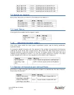
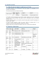
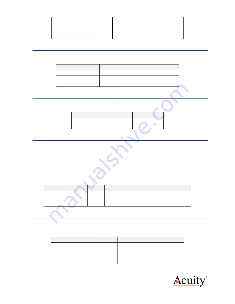
Reg.2; Byte 1567
6 to 0
operating hours counter Bit 13 to 7
Reg.3; Byte 1568
6 to 0
operating hours counter Bit 20 to 14
Reg.4; Byte 1569
6 to 0
operating hours counter Bit 27 to 21
Reg.5; Byte 1570
6 to 0
operating hours counter Bit 31 to 28
7.8
Switch-on Counter
Every time the sensor is turned on, the value will increase to 1.
Register
Bit No.
Meaning
Reg.1; Byte 1571
6 to 0
Switch-on counter Bit 6 to 0
Reg.2; Byte 1572
6 to 0
Switch-on counter Bit 13 to 7
Reg.3; Byte 1573
2 to 0
Switch-on counter Bit 16 to 14
7.9
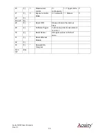
Input Status
This reports the condition of the inputs 1 and 2.
Register
Bit No.
Meaning
Input register.1; Byte
1574
0
Input 1
1
Input 2
7.10
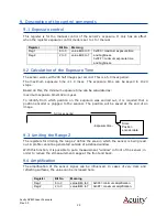
Adjusting the laser output
This is the value which the laser power adjustment control was on during
automatic
operation mode.
To manually adjust this value, aim the scanner to the surface to be scanned. Continue by
reading the value of the laser output control. Now switch the laser adjustment control to
manual
operation mode (see section 8 for how to change values) and write this value
(Output of the adjustment control * 4) into the register “Exposure Control”. The laser
output adjustment control is now adjusted on the object to be measured.
Register
Bit No.
Meaning
Laser adjustment
control Reg.1; Byte
1575
7 to 0
0x00 = maximum exposure time and brightness.
0xFF = minimum exposure time and brightness.
7.11
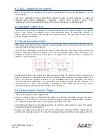
Number of Horizontal and Vertical Pixels
Half of the number of pixels of the sensor in X-direction is indicated as the value "Sensor
Pixel amount horizontal”.
Register
Bit No.
Meaning
Number of Horizontal
pixels Reg.1; Byte 2041
6 to 0
Sensor Number of pixels Bit 6 to 0
Number of Horizontal
pixels Reg.2; Byte 2042
6 to 0
Sensor Number of pixels Bit 13 to 7


