Acuity AP820 Laser Scanners
Rev. 3.3
27
8.
Scanner control
8.1
Data format for Register-addresses and Data
For normal operation, it is not necessary to write the registers. An initialization of the
scanner is not necessary.
The control commands are composed as follow:
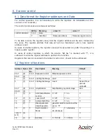
Bit No.
Meaning
value = 0
value = 1
control command
6 to 0
Data
7
Identified
Datas are address
Datas are register value
To be able to write the register value, first the register address will be sent, followed by
the value. The register address that was set will be maintained until a new register
address is sent.
In cases of double registers, the register value will be assumed only after the writing of a
higher-quality register.
In cases of control registers in which the column "Bit No." is marked with "*", it is
sufficient to write the register address to perform the function.
Registers that are not included in the table in section 8.2, should not be addressed.
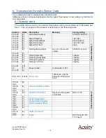
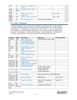
8.2
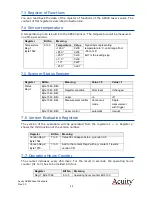
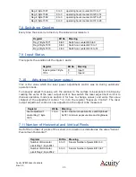
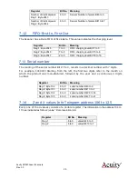
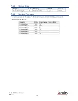
Register of functions
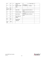
Address
Bytes
Bit
No.
Description
Meaning
Default
0 to 1
[2]
6 to 0
Exposure control
Manual exposure control
0
2 to 3
[2]
4
[1]
6 to 0
Limiting the Range
min Z
0
5
[1]
6 to 0
Limiting the Range
max Z
Sensor Pixel
amount
vertical/8
6 to 7
[2]
6 to 0
Amplification
Amplification grey scale image
500
8 to 10
[3]
11
[1]
0
AGC (amplification
control)
0 = off
1 = on
0
12
[1]
0
Laser on/off
0 = off
1 = on
1
13
[1]
0
Ambient light filter
0 = off
1 = on
0
14
[1]
*
Reset generator
data for position
generator data for position will be
set on "0"
15
[1]
0
Synchronization
Mode
0 =
simultaneous
1 = alternately
0
16 to 17
& 19
[3]
0
18
[1]
0
Scanrate
0 = 195 Hz
1 = 350 Hz
0


