Notes on EMC, ”Ground-Lift” Switch
Notes on EMC (Electromagnetic
Compatibility)
This section is admittedly rather long in pro-
portion to the rest of the manual. Please be
assured that, as a rule, the VSR-5 will not
have problems with interference even if you
don't memorize all the details which we are
about to present. However, in the rare event
that a problem with hum or radio-frequency
interference does occur, we want to offer
enough information to be of real help.
A summary of how to proceed:
1. Set the Ground Lift switch to the ”Hi-Z”
position. That setting will prevent interfer-
ence in most circumstances, and is recom-
mended as the default.
2. Use microphone cables that make no con-
nection between the XLR-3M connector
housing and pin 1. Only the shield of the
cable should be connected with pin 1 at
either end of the cable. For best results,
use the
SCHOEPS
cable K EMC_U.
3. Whenever the outputs of the VSR 5 are
connected to one or more items of other
equipment, only one unit should have a
direct connection between its circuit ground
and AC safety ground. Thus, if necessary,
a ground lift switch on one of the units
should be set to the ”ground” position.
(This does not apply to battery-operated
equipment, nor to AC-operated equip-
ment that is completely isolated from the
electrical safety ground and carries the
symbol .)
4. Power all equipment that is connected to
the VSR 5 from one common AC power
outlet.
Detailed description
In the development of the VSR 5, emphasis
was placed on first-rate audio characteristics
but also on a corresponding degree of immu-
nity to radio-frequency interference (RFI).
Filters for this purpose have been built into
the inputs and outputs, but these protective
measures can reach their full effect only if
suitable cables are used.
To guarantee the best possible protection
from RFI we recommend using special
SCHOEPS
XLR-3 microphone cable such as
K EMC 10 U (10 meters) oder K EMC 20 U
(20 meters). This cable is distinguished by:
– being RF-proof due to its high degree of
shield coverage
– conduction of any RF picked up by the
shield to the chassis of the unit to which
the cable is connected, by means of con-
densers in the output plug – not through
the connection of pin 1 with the connector
housing; this avoids ground loops
– small diameter
– robustness
– non-twisting (important when hanging
microphones)
– flexibility even in cold weather
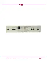
”Ground-Lift” Switch
In conventional XLR-3 cables pin 1 and the
plug housing are often connected together.
This can offer a certain amount of protection
from electromagnetic fields. In that case the
setting of the ”Ground-Lift” switch is imma-
terial since it is bridged by the connection in
the cable plug. But the connection of pin 1
with the connector housing can create
ground loops which can cause hum when
several pieces of equipment share the same
protective AC ground. (What a ground loop
is and what causes it is shown on the fol-
lowing page.) Thus the option exists to sepa-
rate the circuit ground from the chassis
ground by setting the ”Ground-Lift” switch
to the ”LIFT” position. For this to have any
effect, however, the connection in the XLR
plug of the cable between pin 1 and the
9
SCHOEPS
GmbH · Spitalstr. 20 · D-76227 Karlsruhe (Durlach) · Tel: +49 (0)721 943 20-0 · Fax: +49 (0)721 495 750
www.schoeps.de · mailbox@schoeps.de

