VME64x System Subrack 2 U
Assembly
20836-245
www.schroff.biz
11
R1.0, July 14, 2009
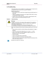
3.2 Rack-Mounting
This subrack system can be installed in 19“ equipment racks. The rack must be
accessible from the front and rear for equipment installation.
Mounting Instructions:
•
Ensure that the rack is constructed to support the weight and dimensions of
the system.
•
Install any stabilizers that came with your equipment rack before mounting
or servicing the system in the rack.
•
Load the rack from the bottom to the top, with the heaviest system at the
bottom, avoid uneven mechanical loading of the rack.
Tabelle 2:
Commissioning
Before the commissioning of the system the following tasks have to be carried
out:
•
Ensure that the system has not been damaged during transport, storage or
assembly.
•
Carry out a new test for the protective earth – set value < 0.1 Ohm
•
Switch on the system and check all VME64x voltages directly on the
backplane before the board assembly.
•
Plug-in the boards
•
Cover the vacant slots with air flow barriers
•
Power-on the system and measure the total input current
•
Swap the fuses at the power input module with fuses that correspond to the
value of the total input current.
Warning!
Voltages over 60 VDC can be present in this equipment. This equipment is
intended to be accessed, to be installed and maintained by qualified and
trained service personnel only.
This eqipment is designed in accordance with protection class 1!
It must therefore be operated only with protective GND/earth connection!
Maximum fuse value is 8 A slow blow.
Summary of Contents for VME64x
Page 1: ...VME64x System Subrack 2 U User s Manual Product No 20836 245 July 14 2009 Doc No 63972245_R1 0...
Page 4: ...VME64x System Subrack 2 U 20836 245 www schroff biz II R1 0 July 14 2009...
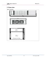
Page 20: ...VME64x System Subrack 2 U Dimensions 20836 245 www schroff biz 16 R1 0 July 14 2009...
Page 21: ......


