


13
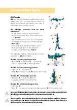
3. Settings.
Settings and adjustments to the product or accessories may only be made
by people who have been given the necessary instructions by a medical
product advisor. Please ensure that none of the user's extremities are in
the respective area when making adjustments of any kind to minimise the
risk of injury.
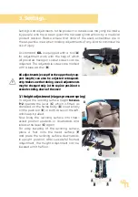
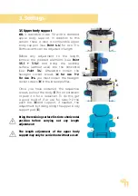
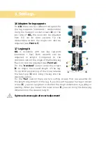
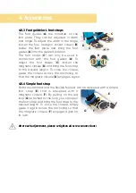
As standard,
till.
is equipped with a tool (
A
)
for adjustment work, with the help of which
all provided hexagon socket screws can be
adjusted. The adjustable screws are marked
with a blue washer (
B
).
All adjustments (except for the upper body sup-
port length) can also be adjusted retrospecti-
vely. Make sure that during use all adjustments
may be changed only in the supine position to
exclude sliding down of the user!
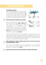
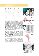
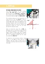
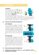
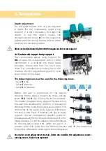
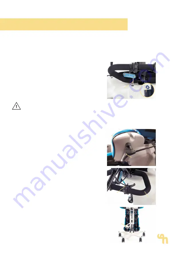
3.1 Height adjustment (via gas pressure spring)
To adjust the reclining surface height
forsizes
1+2
operate the lever (
C
), which is fitted as
standard on the frame body (
D
) or optionally
on the push bar (
E
), in both cases on the left,
and keep it pulled.
Now bring the reclining surface into thed-
esired position upwards or downwards and
release the lever (
C
) again.
For easy lowering of the reclining surface,
place a foot onto the tread surface (
F
)
and press the reclining surface downwards.
In upright position, after successful footrest
adjustment, the height adjustment can be
lowered until the floor.
D
C
F
C
E
A
B


