30
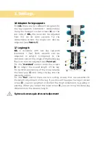
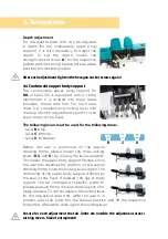
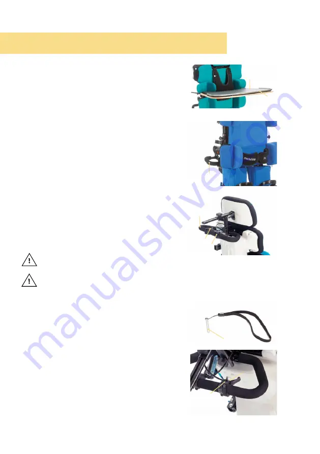
4.9.1 Table support pad
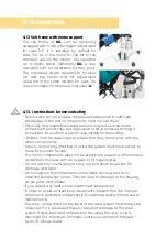
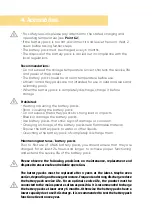
Optionally, a 1 cm high table support pad (
A
)
is available which is covered with a black
flexible fabric and is positioned within the
table edging (
B
).
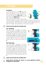
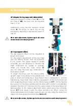
4.10 Push handles / push bars
For
sizes 3 + 4
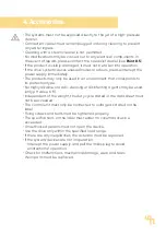
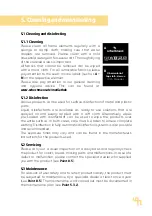
push handles (
C
) are attached
as standard on both sides on the central
column which permit easy pushing in all
directions.
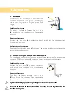
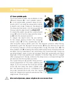
For
sizes 1 + 2
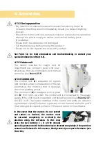
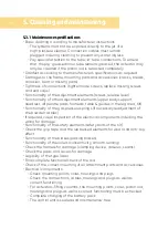
a permanently mounted push
bar (
D
) is optionally available. It is located on
the headrest adapter (or on an adapter if
no headrests is mounted). On this push bare
there is a lever to adjust the angle (
E
- see
Point 3.3
) and, if needed, another lever for to
adjust the height (
F
- see
Point 3.1
). Using the
push bar,
till.
can be pushed in all directions
and the height and angle adjustment can
be supported.
If the product is to be moved together with the
patient, this should be done at the lowest height and in supine position.
If a push bar is mounted the product must only be moved using it.
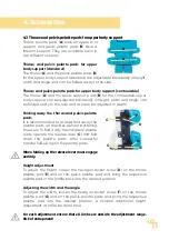
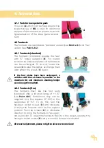
4.11 Safety bolt
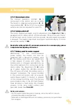
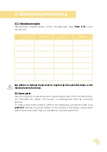
Using the safety bolt (
G
), the reclining
surface is secured against unintentional
angle adjustment (only when adjusting the
angle by means of gas pressure spring - see
Point 3.3
).
Insert the safety bolt (
G
) into the dedicated
hole (
H
) on the release lever (
I
) after having
brought the reclining surface into the desired
position (see
Point 3.3
). Remove the safety
bolt (
G
) again when you want to change the
angle adjustment.
C
4. Accessories.
G
I
H
D
F
E
B
A

