background image

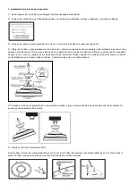
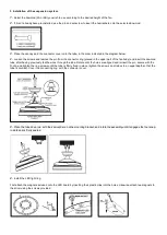
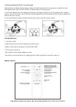
3. Installation of the suspension system.  

1º- Select the downrod (2A or 2B) you wish to use according to the desired height of the fan. 

2º- If it isn´t already been pre-installed, use the pin and set-screw to insert the hemisphere onto the selected downrod.     


3º- Place the canopy and  the connector cover onto the tube, in the order indicated in the diagram below.   

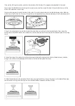
4º- Loosen the screws and remove the pin from the connector ring (placed in the upper part of the fan body) and insert the downrod 
tube, after having previously fed the wires through the tube. Rotate until the holes are aligned and reinsert the pin, secure with the 
R-clip, and tighten the ring screws until the tube is firmly fixed in place (tighten the screws on all sides to an equal depth so that the 
tube is centred). Cover the connecting ring  with the connector cover.  


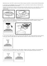
5º- Place the tube down rod  with the semi-sphere  on the mounting bracket, and rotate the assembly until it engages the four snap-
in slots and is firmly seated. 


6º- Install the LED light ring.  

First attach the magnets included onto the LED board by inserting their plastic clips into the holes. Likewise, attach two magnets to 
the driver using the screws provided. 


Summary of Contents for 168328

Page 1: ...ansparente Función temporizador Mando a distancia NOTA SCHULLER RECOMIENDA LA COLOCACIÓN DE PROTECTORES DE SOBRETENSIÓN PARA EVITAR LOS DAÑOS EN LOS COMPONENTES ELECTRÓNICOS DE LA LUMINARIA LED Disponibles en nuestro catálogo Para cualquier duda técnica póngase en contacto con nuestro Departamento Técnico Estamos a su servicio en nuestro email irodriguez schuller es o en nuestro teléfono 961 601 0...

Page 2: ... conector del cuerpo de ventilador 5 Cuerpo del ventilador 6 Circuito de iluminación LED 7 Driver LED 8 Módulo conexión 9 Difusor acrílico 10 Herrajes de instalación incluido imanes y tornillos 11 Mando control remoto 2 Instalación del soporte de montaje Perfore dos orificios en el techo con una profundidad adecuada con una broca de diámetro 8 mm e inserte 2 piezas de tornillos de expansión para t...

Page 3: ... de él previamente Gírelo hasta coincidir los orificios y vuelva a insertar el pasador asegúrelo con el clip R y apriete los tornillos del aro hasta inmovilizar el tubo apriete los tornillos por todos los lados con similar profundidad para que el tubo quede centrado Cubra el aro de unión con la tapa del aro 5º Coloque el tubo con la semiesfera en el soporte de montaje y gire el conjunto hasta que ...

Page 4: ...o al soporte de montaje del techo conecte el módulo a los cables que salen del ventilador por la parte superior Después conecte el cable de red con los cables INPUT del Módulo Una vez conectados todos introduzca el módulo en el espacio reservado en el soporte de montaje del techo 8º Levante el canopí hasta el techo para cubrir el soporte de montaje asegúrese que el canopí se asiente en los dos tor...

Page 5: ... problema de oscilación aún se nota Repita esto hasta encontrar el lugar que permitirá que desaparezca el problema de la oscilación 2º Quite las piezas del imán de equilibrio y coloque la tira adhesiva en su posición Figura B SOLUCIÓN DE PROBLEMAS Si el ventilador no arranca Compruebe las conexiones de los cables al ventilador asegúrese de que estén todas correctas Compruebe y asegúrese de que la ...

Page 6: ...etractable blades in clear acrylic Timer function Remote control NOTE SCHULLER RECOMMENDS TO PLACE SURGE PROTECTORS TO AVOID DAMAGES TO THE ELECTRONIC COMPONENTS OF THE LED LUMINAIRE Available in our catalogue If you have any technical questions please do not hesitate to contact our technical Department We are at your disposal in our emai irodriguez schuller es ...

Page 7: ...B long 3 Canopy 4 Connector cover 5 Fan body 6 LED light ring 7 LED driver 8 Connector module 9 Light shade Acrylic diffuser 10 Screws pack installation tools including magnets and screws 11 Remote control 2 Installation of the ceiling mount bracket Drill two acquired deep holes into the ceiling using a 8mm drill bit and insert two expansion or 4 plaster screws bolts into the holes Then fix the ce...

Page 8: ...after having previously fed the wires through the tube Rotate until the holes are aligned and reinsert the pin secure with the R clip and tighten the ring screws until the tube is firmly fixed in place tighten the screws on all sides to an equal depth so that the tube is centred Cover the connecting ring with the connector cover 5º Place the tube down rod with the semi sphere on the mounting brack...

Page 9: ...he ideal placement 7º Next to the ceiling bracket connect the module to the wires that come out from the top downrod topside Then connect the network cable to the INPUT cables of the module Once all are connected insert the module into the reserved space on the ceiling mount 8º Raise the canopy to the ceiling to cover the ceiling mount ensuring the canopy rests on the two bracket screws rotate the...

Page 10: ...peat this until you find the position that corrects the wobble and allows the fan to run smoothly 2º Remove the balance magnets and attach the balance kit in order to stick them in place Figure B TROUBLESHOOTING 1 The fan won t start Check the fan wiring ensure all the cables are connected correctly Check and ensure that the input power is correct at 220V 50HZ 2 The fan makes a loud noise Ensure a...

Reviews: