Warn
l. This
2. Th
3. To
INST
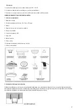
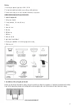
1. Li
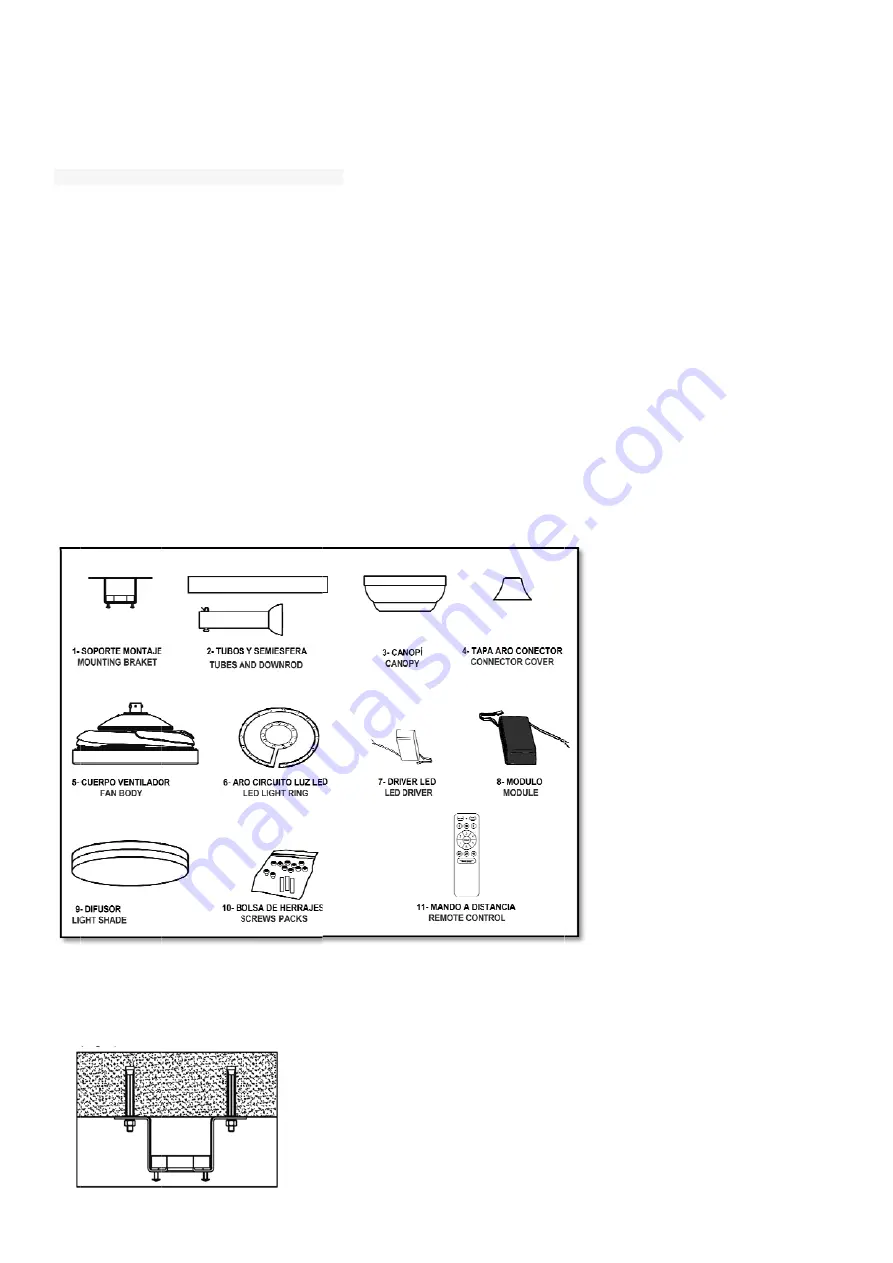
1- Ce
2 –Ca
3- Ca
4- Co
5- Fa
6- LE
7- LE
8- Co
9- Lig
10- S
11- R
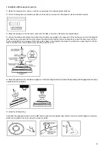
2. In
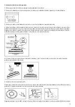
Drill
Then
ning:
s ceiling fan req
e electrical insta
o reduce risk of i
TRUCTIONS A
st of compon
eiling-mount bra
anopy downrod
anopy
onnector cover
an body
ED light ring
ED driver
onnector module
ght shade ( Acry
Screws pack (ins
Remote control
nstallation of
two acquired
n, fix the ceilin
quires a power i
allation should b
injury, do not to
AND INSTALL
nents
acket
s ( 2A: short y
e
ylic diffuser)
stallation tools:
the ceiling-m
deep holes int
ng-mount brac
nput of 220 V /
be carried out b
uch the blades
LATION STEP
2B: long)
including magn
mount bracke
to the ceiling,
cket onto the e
1-CEIL
50 HZ.
by a qualified ele
while the fan is
PS.
nets and screws
et:
using a 8mm
expansion bolt
LING-MOUNT B
ectrician.
in operation.
s)
drill bit, and in
ts and tighten
BRACKET
nsert two expa
the nuts until
ansion or 4 pla
the bracket is
aster screws b
firmly fixed to
bolts into the h
o the ceiling.
7
holes.

