background image

ASSEMBLY

SRW1000   08/17

Assembly Section 3-3

© 2017 Alamo Group Inc. 

ASSEMBL

Y

3. Remove shipping brackets and mount plates.

4. The lower drum clamps are used to assemble the machine. The rest of the brackets can be discarded.

Summary of Contents for SRW1000

Page 1: ...n Canada S0K 1N0 Tel 306 287 3715 Fax 306 287 3355 Parts Fax 306 287 4066 Web www schulte ca PIVOTING ROCK WINDROWER This Operator s Manual is an integral part of the safe operation of this machine and must be maintained with the unit at all times READ UNDERSTAND and FOLLOW the Safety and Operation Instructions contained in this manual before operating the equipment C01 Cover ...

Page 2: ... safety equipment properly attached to minimize the chance of accidents BEFORE YOU START Read the safety messages on the implement and shown in your manual Observe the rules of safety and common sense WARRANTY INFORMATION Read and understand the complete Warranty Statement found in this Manual Fill out the Warranty Registration Form in full and return it to within 30 Days Make certain the Serial N...

Page 3: ...y decals are in good condition replace if necessary ____Check that gearboxes have been filled with oil ____Check that all grease fittings have been lubricated DEALER S DELIVERY GUIDE for the SCHULTE SRW1000 ____Mounting and removal from tractor ____Operation ____Adjustments ____Lubrication ____Maintenance ____Operator s safety precautions ____User s responsibility and warranty ____Operator s manua...

Page 4: ......

Page 5: ...n Tightener 3 9 Transport Lock Pin 3 10 Driveline Shield Chains 3 10 Light Kit 3 11 Installation of Left Light Bar 3 11 Installation of the Right Light Bar 3 11 Installation of Lights 3 11 PRE DELIVERY CUSTOMER CHECKLIST 3 12 OPERATION SECTION 4 1 STANDARD EQUIPMENT SPECIFICATIONS 4 3 OPERATOR REQUIREMENTS 4 3 TRACTOR REQUIREMENTS 4 4 ROPS and Seat Belt 4 4 Tractor Safety Devices 4 5 Tractor Horse...

Page 6: ...Operation 4 26 Shutting Down the Implement 4 27 DISCONNECTING THE WINDROWER FROM THE TRACTOR 4 28 WINDROWER STORAGE 4 29 TRANSPORTING THE TRACTOR AND IMPLEMENT 4 30 Transporting on Public Roadways 4 31 Hauling the Tractor and Implement 4 34 TROUBLESHOOTING GUIDE 4 36 MAINTENANCE SECTION 5 1 NUTS AND BOLTS 5 2 Bolt Grades and Torque 5 2 DRIVE CHAIN 5 3 WINDROWER TEETH 5 3 DRIVELINE SHIELDS 5 3 DRUM...

Page 7: ...Safety Section 1 1 2017 Alamo Group Inc SAFETY SECTION ...

Page 8: ... are intended to warn the owner operator of impending hazards and the degree of possible injury faced when operating this equipment Indicates an imminently hazardous situation that if not avoided WILL result in DEATH OR VERY SERIOUS INJURY Indicates an imminently hazardous situation that if not avoided COULD result in DEATH OR SERIOUS INJURY Indicates an imminently hazardous situation that if not ...

Page 9: ...rator has fully read and understood the manuals prior to operation SG 4 The operator and all support personnel should wear hard hats safety shoes safety glasses and proper hearing protection at all times for protection from injury including injury from items that may be thrown by the equipment SG 16 PROLONGED EXPOSURE TO LOUD NOISE MAY CAUSE PERMANENT HEARING LOSS Tractors with or without an Imple...

Page 10: ...atigue affecting safe operation Take scheduled work breaks to help prevent these potentially impaired operating conditions Never operate the Implement and Tractor in a fatigued or bored mental state which impairs proper and safe operation SG 32 Avoid contact with hot surfaces including hydraulic oil tanks pumps motors valves and hose connections Relieve hydraulic pressure before performing mainten...

Page 11: ...ou have clear visibility in daylight or with adequate artificial lighting Never operate in darkness or foggy conditions where you cannot clearly see at least 100 yards in front and to the sides of the tractor and implement Make sure that you can clearly see and identify passersby steep slopes ditches drop offs overhead obstructions power lines debris and foreign objects If you are unable to clearl...

Page 12: ...r death Read the Tractor operators manual for proper starting instructions SG 13 Do not operate this Equipment with hydraulic oil or fuel leaking Oil and fuel are explosive and their presence could present a hazard Do not check for leaks with your hand High pressure oil streams from breaks in the line could penetrate the skin and cause tissue damage including gangrene To check for a hose leak SHUT...

Page 13: ...ctures Such impact could cause the broken objects to be thrown outward at very high velocities To reduce the possibility of property damage serious injury or even death never allow the cutting blades to contact such obstacles SGM 4 Never leave the Power Unit and Implement unattended while the Implement is in the lifted position Accidental operation of the lifting lever or a hydraulic failure may c...

Page 14: ...ement input driveline to the Tractor PTO it is important that the connecting yoke spring activated locking collar slides freely and the locking balls are seated securely in the groove on the Tractor PTO shaft Push and pull the driveline back and forth several times to ensure it is securely attached A driveline not attached correctly to the Tractor PTO shaft could come loose and result in personal ...

Page 15: ...ed through the turn only after you determine that the equipment can be operated at a higher speed Use extreme care and reduce your speed when turning sharply to prevent the tractor and implement from turning over Determine the maximum turning speed for you and this equipment before operating on roads or uneven ground Only transport the Tractor and Implement at the speeds which allow you to properl...

Page 16: ...eling on public roads and when storing STL 15 Relieve hydraulic pressure prior to doing any maintenance or repair work on the Implement Place the Implement on the ground or securely blocked up disengage the PTO and turn off the tractor engine Push and pull the Remote Cylinder lever in and out several times Disconnect and remove the Implement hydraulic hoses from the tractor prior to starting any m...

Page 17: ... even death SG 35 PARTS INFORMATION Schulte Products use balanced and matched system components for blade carriers blades cuttershafts knives knife hangers rollers drivetrain components and bearings These parts are made and tested to Schulte Industry specifications Non genuine will fit parts do not consistently meet these specifications The use of will fit parts may reduce the performance void Sch...

Page 18: ...laced at once to reduce the possibility of injury or death from thrown objects entanglement or blade contact SSM 07 In addition to the design and configuration of this Implement including Safety Signs and Safety Equipment hazard control and accident prevention are dependent upon the awareness concern prudence and proper training of personnel involved in the operation transport maintenance and stor...

Page 19: ...SAFETY SRW1000 08 17 Safety Section 1 13 2017 Alamo Group Inc SAFETY Decal Location ...

Page 20: ... 226 153 2 REFLECTOR Red Reflector 2 x 9 7 226 1531 2 REFLECTOR Red Reflector 2 x 4 1 2 8 226 154 1 REFLECTOR Amber Reflector 2 x 9 9 226 1541 1 REFLECTOR Amber Reflector 2 x 4 1 2 10 226 181 7 INSTRUCT 8 Hour Grease Interval 11 226 182 5 INSTRUCT 50 Hour Grease Interval 12 226 183 1 INSTRUCT 8 Hour Oil Interval 13 226 189 2 REFLECTOR Fluorescent Reflector 2 x 9 14 226 374 1 DANGER Multi Hazard 15...

Page 21: ...SAFETY SRW1000 08 17 Safety Section 1 15 2017 Alamo Group Inc SAFETY Decal Description ...

Page 22: ...SAFETY SRW1000 08 17 Safety Section 1 16 2017 Alamo Group Inc SAFETY ...

Page 23: ...SAFETY SRW1000 08 17 Safety Section 1 17 2017 Alamo Group Inc SAFETY ...

Page 24: ...SAFETY SRW1000 08 17 Safety Section 1 18 2017 Alamo Group Inc SAFETY ...

Page 25: ...SAFETY SRW1000 08 17 Safety Section 1 19 2017 Alamo Group Inc SAFETY ...

Page 26: ...SAFETY SRW1000 08 17 Safety Section 1 20 2017 Alamo Group Inc SAFETY ...

Page 27: ...nect the power source and wait for all machine movement to stop before servicing adjusting cleaning or unclogging the equipment except where the machine must be running to be properly serviced or maintained in which case the employer shall instruct employees as to all steps and procedures which are necessary to safely service or maintain the equipment Make sure everyone is clear of machinery befor...

Page 28: ......

Page 29: ...Introduction Section 2 1 2017 Alamo Group Inc INTRODUCTION SECTION ...

Page 30: ...s of this implement read this manual or be instructed of its contents as to safety proper operation and maintenance before beginning operation Your windrower has been assembled for operation with a tractor PTO input speed of 540 RPM When ordering replacement parts for the Gearboxes and the Drivelines be sure to specify the serial number The serial number is located on the left hand side attached t...

Page 31: ...ll out the Warranty Card in full Be sure to answer all questions including the Serial Number of the windrower Mail within 30 days of delivery date of this implement NOTE Warranties are honored only if completed Owner Registration and Warranty forms are received by Schulte within thirty days of delivery of the implement 3 Record the Windrower Model and Serial Numbers on the Warranty page at the fro...

Page 32: ......

Page 33: ...Assembly Section 3 1 2017 Alamo Group Inc ASSEMBLY SECTION ...

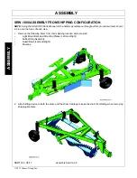
Page 34: ...ence throughout this procedure Items shown in blue are the focus of each step 1 Remove the following items from their shipping location and set aside Light Mount Bars and Mounting Plates Left and Right Rubber Flap Assembly Guard Rods Left and Right Driveline 2 Attach lifting device to both the drum and the Drum Carriage to keep the drum from falling when removing shipping brackets ...

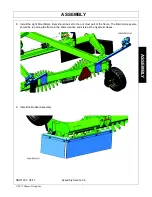
Page 35: ...Y SRW1000 08 17 Assembly Section 3 3 2017 Alamo Group Inc ASSEMBLY 3 Remove shipping brackets and mount plates 4 The lower drum clamps are used to assemble the machine The rest of the brackets can be discarded ...

Page 36: ... 5 Lower the Drum and Drum Carriage 6 Raise Drum and Carriage assembly into place and attach with drum clamps that were removed in step 4 7 Install the Hydraulic Cylinder to the Drum Carriage and Main Frame Clamp Hydraulic Hoses to the main frame using the bolts on the frame ...

Page 37: ...17 Alamo Group Inc ASSEMBLY 8 Install the Light Mount Bars Bars should be set to the out most part of the frame The Main Harness wire should be run along the frame in the same location and style as the Hydraulic Hoses 9 Install the Rubber Assembly ...

Page 38: ...ASSEMBLY SRW1000 08 17 Assembly Section 3 6 2017 Alamo Group Inc ASSEMBLY 10 Install Driveline 11 Install Rod Guards one on each side of drum ...

Page 39: ...osen the bolts and re install with the wheels to the outside of the frame OPERATING POSITION shown below The center of the lower 5 8 mounting bolts must be set to a maximum 2 1 4 from the bottom of the pivoting wheel standard legs as shown below A setting higher than 2 1 4 may result in the tires contacting the drum Also see Operating the Windrower in the Operation Section of this manual ...

Page 40: ...bolts are in place and properly tightened Refer to the Maintenance Section of this manual for proper bolt grades and torques Check that the wheel standard axle plates are set properly The center of the lower 5 8 mounting bolts must be set to a maximum 2 1 4 from the bottom of the pivoting wheel standard legs as shown below A setting higher than 2 1 4 may result in the tires contacting the drum Che...

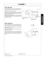
Page 41: ... out bolts Slide the appropriate amount of machine bushings until they are flush with end of shaft then cap off and tighten end bolt Chain Tightener Align small sprocket to drum sprocket with machine bushings Tighten the set screws and install chain Finger tighten the center M16 bolt for the Rosta tightener into side plate Align tightener sprocket with other sprockets by adjusting the half nuts Us...

Page 42: ...g position The lock up pin can then be stored and secured with the snap pin as shown Driveline Shield Chains Attach PTO shield chain to tractor or windrower hitch allowing sufficient slack for turning OSHA ASABE and SAE standards require that all rotating shafts be guarded against contact The unchained plastic shields can rotate with the driveline but must stop when they contact another object Not...

Page 43: ...gh backing plate and light bar Secure with 1 2 locknuts provided Installation of the Right Light Bar 1 Locate the light bar R900 117 is the longer of the two 2 Place the light bar on the back of the machine wi th the arm pointing to th outside of the machine 3 Place a backing plate R900 118 on opposite side of tube inside of machine from light bar Position the light bar and backing plate as close ...

Page 44: ...all hoses tight and do not leak Are all decals in place See manual for decal description and placement Are all bolts tight Have all hoses been properly routed so that hoses do not kink or bind when windrower is articulated through all motions Is machine equipped with proper operator protection Is drum rotation correct Are teeth hard surfaced Does implement operate smoothly at normal operating spee...

Page 45: ...Operation Section 4 1 2017 Alamo Group Inc OPERATION SECTION ...

Page 46: ...1000 windrower and are not necessarily of a SRW1000 windrower Some pictures may show shields removed for picture clarity NEVER OPERATE these implements without all shields in place and in good operational condition The operator must be familiar with the SRW1000 and tractor operation and all associated safety practices before operating the SRW1000 and tractor Proper operation of the SRW1000 windrow...

Page 47: ...manual safety signs are affixed to the implement and tractor If any part of the operation and safe use of this equipment is not completely understood consult an authorized dealer for a complete explanation If the operator cannot read the manuals for themselves or does not completely understand the operation of the equipment it is the responsibility of the supervisor to read and explain the manuals...

Page 48: ...lement Drugs and alcohol will affect an operator s alertness and coordination and therefore affect the operator s ability to operate the equipment safely Before operating the Tractor or Implement an operator on prescription or over the counter medication must consult a medical professional regarding any side effects of the medication that would hinder their ability to operate the Equipment safely ...

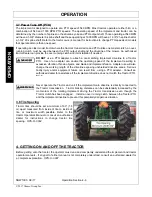
Page 49: ...port positions or working position The hydraulic cylinders are operated by the tractors hydraulic pump The tractor requires a 5 gpm 1800 PSI dual remote outlet 3 2 Tractor Safety Devices If transporting or operating the tractor and implement near a public roadway the tractor must be equipped with proper warning lighting and a Slow Moving Vehicle SMV emblem which are clearly visible from the rear o...

Page 50: ... the momentum of the rotating implement driving the Tractor transmission even though the Tractor clutch has been engaged Install an over running clutch between the Tractor PTO and the implement driveline to prevent this potentially dangerous situation DO NOT use a PTO adapter to attach a non matching Implement driveline to a Tractor PTO Use of an adapter can double the operating speed of the Imple...

Page 51: ...te the controls easily SG 11 Never allow children or other persons to ride on the Tractor or Implement Falling off can result in serious injury or death SG 10 4 2 Dismounting the Tractor Before dismounting park the tractor and implement on a reasonably level surface apply the parking brake idle the engine down disengage the PTO and lower the implement to the ground Shut down the tractor engine acc...

Page 52: ...d service according to the tractor operator s manual Make sure all guards shields and other safety devices are securely in place The parking brake is on The PTO control lever is disengaged The 3 point hitch control lever is in the lowered position The hydraulic remote control levers are in the neutral position The tractor transmission levers are in park or neutral Refer to the tractor owner s manu...

Page 53: ... the hitch pin through the drawbar and tongue clevis Once the pin is inserted attach the snap ring pin through the hole on the hitch pin and snap in place 5 Attach safety tow chain to implement and tractor Fasten the large loop of the safety chain to the hitch Then pass hook end of safety chain through the large loop Refer to you tractor operator s manual for complete instructions to attach to tra...

Page 54: ...be connected between the tractor and implement This will help control the implement in the event the tongue becomes disconnected from the drawbar Make sure the chain is attached to a secure location on the tractor and not to an intermediate support After connecting both ends of the safety chain drive the tractor to the right and left to check for proper chain length Adjust length as necessary and ...

Page 55: ...E The rock windrower must be in working position before the drum can be adjusted To adjust the drum the following procedure is recommended 1 First find a level piece of ground or concrete pad to set the machine on 2 Ensure machine is in working position and locking pin is installed as shown in Figure Asm RW 0007 Ensure that no one is near the machine while hydraulics are being created 3 Lower the ...

Page 56: ... inspecting that all safety devices are equipped and functional and performing needed repairs Do not operate the windrower and tractor if the pre operation inspection reveals any condition affecting safe operation Perform repairs and replacement of damaged and missing parts as soon as noticed By performing a thorough pre operation inspection and service valuable down time and repair cost can be av...

Page 57: ...rom not maintaining this machine in good working order SG 21 9 1 Tractor Pre Operation Inspection Service Refer to the tractor operator s manual to ensure a complete pre operation inspection and scheduled service is performed according to the manufacturers recommendations The following are some of the items that require daily service and inspection Tire condition air pressure Wheel lug bolts Steer...

Page 58: ...tor drawbar with a proper size pin Ensure that a properly rated safety tow chain is equipped securing the windrower to the tractor Check that the main driveline is securely attached to the tractor and the locking collar is seated in the groove of the PTO shaft Ensure the divider drivelines are secure at both ends OPS W 0015 Ensure the drum roller is in good condition and rotate freely Ensure the d...

Page 59: ...the height of the lower level plug located in the side of the gearbox A low oil level is a warning sign that the gearbox may be cracked or its seal is damaged and needs to be replaced Ensure all gearbox vents are in place and free from clogs OPS W 0009_A Ensure hydraulic cylinder is installed and retained correctly Ensure the proper size pins are used to retain the cylinder in place and are secure...

Page 60: ...ct windrower tire condition wheel bearings and lug nut torque OPS W 0011_C Inspect the windrower teeth and make sure that they are hard surfaced and that the bare tooth is not exposed If the hard surfacing is not properly maintained highly accelerated tooth wear will result OPS W 0012 ...

Page 61: ...rt of Shift Specific Comments if not O K The flashing lights function properly The SMV Sign is clean and visible The tires are in good condition with proper pressure The wheel lug bolts are tight The tractor brakes are in good condition The steering linkage is in good condition There are no visible oil leaks The hydraulic controls function properly The ROPS or ROPS Cab is in good condition The sea...

Page 62: ...s in the canister on the implement All safety decals are in place and legible The hitch connection bolts pins are tight Tongue hitch connection bolts pins are tight There are no cracks in tongue or hitch Tow chain is properly attached to the tractor implement The hydraulic cylinders pins are properly retained There are no leaking or damaged hoses The Driveline clutch is in good condition not froze...

Page 63: ...ing distance increases Determine the maximum transport speed not to exceed 20 mph 30 kph for transporting this equipment Test the equipment at a slow speed in turns Increase the speed through the turn only after you determine that the equipment can be operated at a higher speed Use extreme care and reduce your speed when turning sharply to prevent the tractor and implement from turning over Determ...

Page 64: ... the lowered position and the PTO is disengaged before starting the tractor OPS W 0005 10 2 Brake and Differential Lock Setting Make sure the tractor brakes are in good operating condition Tractor brakes can be set to operate independently allowing single rear wheel braking action or locked together to provide simultaneous rear wheel braking FOR MOST DRIVING AND OPERATING CONDITIONS THE BRAKE PEDA...

Page 65: ... slopes and turning corners Rear tractor tire spacing should be increased when working on inclines or rough ground to reduce the possibility of tipping Use extreme caution when operating on steep slopes Keep the tractor in a low gear when going downhill DO NOT coast or free wheel downhill Allow sufficient clearance for the Implement to swing outward while turning Implements carried behind the Trac...

Page 66: ...iveline is at its extreme shortest length This type of abusive operation can cause serious damage to the tractor and mower drive by pushing the PTO into the tractor and through the support bearings or downward onto the PTO shaft breaking it off When confronted with an incline or ditch do not approach from an angle which is perpendicular or straight on as damaged to over collapse of the driveline m...

Page 67: ...any operation the operator must become familiar with the area to be windrowed and any obstacles and hazards contained within to ensure safety to the operator bystanders and equipment Special attention should be paid to foreign debris rough terrain steep slopes and passersby and animals in the area Inclines and ditches should be approached along a line which is at an angle as shown This type of pat...

Page 68: ... Inspect the condition of the implement and make any needed repairs immediately Make sure the teeth on drum is not damaged before resuming operation Always wear your seat belt securely fastened and only operate the tractor and windrower with the ROPS in the raised position If the tractor or windrower hits a tree stump or bump a sudden movement could throw you off of the seat and under the tractor ...

Page 69: ...ound speed Make sure that the windrower is operating at its full rated speed before entering the field to be windrowed If it becomes necessary to temporarily regulate engine speed increase or decrease the throttle gradually Ground speed is achieved by transmission gear selection and not by the engine operating speed The operator may be required to experiment with several gear range combinations to...

Page 70: ... windrow reduce the working depth The axle plates can also be adjusted up or down to bias the working depth to one side or the other Typically the axle of the right leg on the pivoting wheel standard is set 1 lower then the left leg This is to help bring material to the surface If large rocks are being carried into the windrow slow the tractor rpm 12 Roadside Operation The axle on the left side of...

Page 71: ...l other overhead and ground obstructions while you are windrowing Use extreme care to avoid hitting these types of obstructions 12 1 Shutting Down the Implement To shut down the implement first bring the tractor to a complete stop Then slow down the windrower by reducing the engine speed before disengaging the PTO Wait for all rotating motion to stop before proceeding to drive or shut down the tra...

Page 72: ...isconnecting windrower the tractor should be completely shut down and secured in position Relieve hydraulic pressure by moving the control levers back and forth several times 2 Lower the parking jack and raise the windrower until the tongue clevis is no longer resting on the tractor drawbar and is supported solely by the jack Make sure the jack foot is securely resting at ground level or securely ...

Page 73: ...to maintaining its appearance and to help ensure years of dependable service The following are suggested storage procedures Thoroughly clean all dirt or debris off the implement to prevent damage from rotting grass and standing water Lubricate all implements points as detailed in the maintenance section Tighten all bolts and pins to the recommended torque Check the implement for worn and damaged p...

Page 74: ...he possibility of accidents while moving between locations can be substantially minimized OPS U 0017 Never allow children or other persons to ride on the Tractor or Implement Falling off can result in serious injury or death SG 10 Before transporting the tractor on a public roadway or boarding a trailer for transport the tractor brake pedals should be locked together Locking the pedals ensures tha...

Page 75: ...Be extremely cautious when the piece of equipment that you are towing is wider than the tractor tire width and or extends beyond your lane of the road In wet conditions where there is a likelihood of material collecting on the Implement make certain that this material is removed before traveling on public roadways STL 7 Never allow children or other persons to ride on the Tractor or Implement Fall...

Page 76: ...llow all following traffic to pass Do not exceed the legal speed limit set in your country for agricultural tractors Always stay alert when transporting the tractor and implement on public roads Use caution and reduce speed if other vehicles or pedestrians are in the area OPS U 0022 Reduce speed before turning or applying the brakes Ensure that both brake pedals are locked together when operating ...

Page 77: ...the tractor s weight is on the front wheels to maintain safe steerage Slow down on rough or uneven surfaces STI 01 Only tow the Implement behind a properly sized and equipped Tractor which exceeds the weight of the Implement by at least 20 DO NOT tow the Implement behind a truck or other type of vehicle Never tow the Implement and another Implement connected in tandem Never tow the Implement at sp...

Page 78: ...n turns Increase the speed through the turn only after you determine that the equipment can be operated at a higher speed Use extreme care and reduce your speed when turning sharply to prevent the tractor and implement from turning over Determine the maximum turning speed for you and this equipment before operating on roads or uneven ground Only transport the Tractor and Implement at the speeds wh...

Page 79: ... so that when tightened the chains are pulling downward and against themselves Carefully tighten the securing chains or other fasteners using boomers or binders to apply maximum tension Use extreme care when attaching and removing the securing devices as the extreme tension involved when released has the potential to inflict serious injury While hauling the tractor and implement make occasional st...

Page 80: ...mproper pivoting procedure Refer to pivoting instructions and repeat steps Too much drawbar load Adjust transport wheel or hitch clevis to remove weight from hitch pole Accelerated wear of Inadequate greasing Carefully follow greasing instructions universal joint cross Accelerated wear of Inadequate greasing Carefully follow greasing instructions universal joint sliding members Torque limiter slip...

Page 81: ...Maintenance Section 5 1 2017 Alamo Group Inc MAINTENANCE SECTION ...

Page 82: ...tter pins roll pins and other fasteners weekly and replace if necessary Bolt Grades and Torque When replacing damaged bolts use only plated Grade 5 bolts unless otherwise specified Use only bolts of the correct length Refer to the Parts section Do not replace lock nuts with nuts and lock washers Use only original equipment lock nuts Recommended Torques in foot pounds for SAE Grade 5 bolts based on...

Page 83: ...erial has been worn off Once the hard surface material is gone wear to the base metal of the teeth will be very rapid CX170 hard surfacing electrodes are recommended DRIVELINE SHIELDS The plastic cones shielding the slip clutch and shear bolt need to be periodically frequently cleaned Stop the tractor engine disconnect the PTO shaft and remove any debris that has accumulated inside the shield DRUM...

Page 84: ...ated with grease Spread grease on the outside of the bearing with your gloved finger Ensure that no dirt or filings contact the grease or the bearings 2 Pack the inside of the hub completely with grease 3 Apply grease on both races 4 Install the large bearing into the back of the hub and rotate the bearing several times 5 Install the dust grease seal using the right size seal driver Spread a film ...

Page 85: ...sh installing the cotter pin by bending the ends 4 Coat the inside of the dust cap with a thin coat of grease by using your gloved finger Then install on hub using the right dust cap driver 5 Wipe off all excess grease from hub and axle There should not be any drag noticed when spinning a tire installed on a hub If the axle nut is too tight the rollers of the wheel bearings will remove the grease ...

Page 86: ...linked to the slip clutch This allows the slip clutch to float so the adjustment can be made Secure the retaining bolt after the slip clutch is adjusted If the rock wonderer has been left unused for a period of time e g A month or even less in damp wet conditions the clutch friction liners may tend to bond to the clutch plates To free up the friction liners the clutch springs should be backed off ...

Page 87: ...x after the first 50 hours of operation then yearly Check gearbox oil level frequently Steady loss of oil will indicate damaged seals which should be replaced immediately to prevent ruining the gearbox Gearbox oil should be maintained to the height of the lower level plug located in the side of the gearbox Procedure for refilling of gearboxes 1 Park unit on a level surface 2 Remove drain plug from...

Page 88: ...SAE 80 90 Gear Oil Grease Schedule Grease should meet the following recommendations SAE Multi purpose grease SAE Multi purpose grease containing 3 to 5 percent molybdenum disulfide Use SAE NLGI 2 IMPORTANT Before attaching the driveline clean and grease the tractor PTO and the Implement shaft ...

Page 89: ...ons All flange bearings are permanently lubricated However grease fittings are provided on the external units Grease should be pumped into the bearing until it is seen purging at the clearance between the outer race and slinger Wheel Hubs Wheel Hubs Yearly Fill until grease is seen purging at the axle seals Drive Chain Apply light grease or oil to the drive chain after every 8 hours of operation O...

Page 90: ......

Page 91: ... against manufacturer s defects only Coverage includes parts and labor For Rental Use Component and Driveline Warranty is 30 Days from within the first in service date Structural warranty is 30 Days from within the first in service date Tires and Rims are covered for 1 year against manufacturer s defects only Coverage includes replacement parts and labor Where legislation allows The dealer is resp...

Page 92: ...ested by the manufacturer to verify that the goods are defective in material or workmanship The Dealer must keep the failed part until the claim is processed to allow Schulte Industries the option of further examination of the part Further examination may mean that pictures are sent or that the part be returned to Schulte A Return Goods Authorization RGA must be sent with any returned part If a fa...

Page 93: ......
Page 94: ...SRW1000 08 17 P N R900 010C Printed Canada ...

Reviews: