background image

9

AIR COMPRESSOR - OWNER'S MANUAL

AIR COMPRESSOR - OWNER'S MANUAL

40

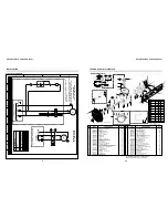
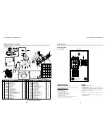
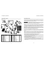
INSTALLATION

K1

1 L1

3 L2

5 L3

A1

A2

96 NC

95 NC

X1

FT1

PE

L3

L1

L1: "PHASE 1" CONDUCTOR

L2: "PHASE 2" CONDUCTOR

L3: "PHASE 3" CONDUCTOR

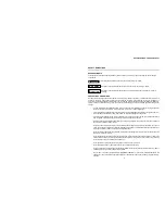
MAKE LEADS "L1", "L2", "L3" AND "PE" TO "1 L1", "3 L2",

MANUFACTORY WIRES LEADS:

"96 NC" CONECTED TO "A1"

"5 L3" CONECTED TO "A2" *

"1 L1" CONECTED TO "RED BUTTON" **

"RED BUTTON" CONECTED TO "X1.2"

"X1.2" CONECTED TO "PRESSURE SWITCH"

"PRESSURE SWITCH" CONECTED TO "X1.1"

"X1.1" CONECTED TO "95 NC"

2 T1

4 T2

6 T3

"X1.4" AND "X1.5" CONECTED TO "PRESSURE SWITCH" AND "MOTOR"

"2 T1", "4 T2" AND "6 T3" CONECTED TO "MOTOR"

CUSTOMER WIRES LEADS:

L2

PE: "PROTECTIVE" CONDUCTOR (GROUND)

"5 L3" AND "X1.3" RESPECTIVELY, KEEPTING THE OTHERS CONDUCTORS;

WARNING:

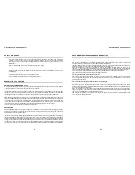
- COMPRESSOR FLYWHEEL ROTATION SHOULD BE COUNTERCLOCKWISE

WHEN FACING FLYWHEEL

- IF COMPRESSOR FLYWHEEL ROTATION IS REVERSED (CLOCKWISE), QUICLY

TURN OFF THE POWER AND DISCONNECT ALL SUPPLY SOURCE AND

INTERCHANGE THE "L1" AND "L2" WIRES.

NOTE

:

The

wiring procedure

is only for reference also

Electrical Diagram

see page 5.

* For the product version in 460V:

The command wiring is carried out by a step-down transformer from 460V to 230V
as showed on page 5 by T

.

- TURN OFF POWER BEFORE SERVICING

X1

THREE - PHASE

1 2

1 2

3 4 5

3 4 5

WIRING PROCEDURE
D.O.L. STARTER

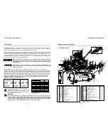
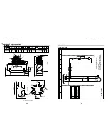
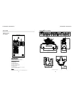
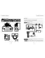
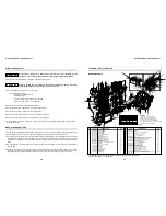
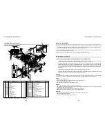
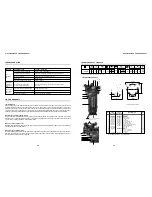
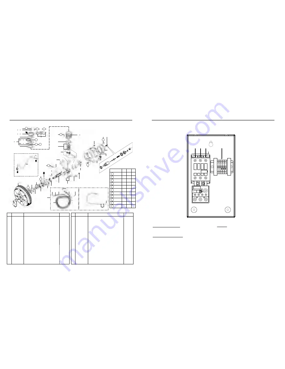
TECHNICAL DATA 10120HW40X

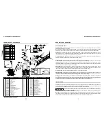
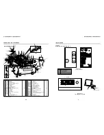
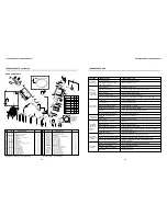
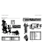
BARE PUMP PARTS

TABLE 1 - TORQUE
ESPECIFICATION FOR BOLTS

HP 4.3/4" ring kit
Upper gasket kit
HP 90 mm valve plate kit
LP 4.3/4" cylinder
HP 90 mm cylinder
LP 4.3/4" valve plate kit
LP 4.3/4" valve plate
HP 90 mm valve plate
LP 4.3/4" cylinder cover with breather
LP 4.3/4" cylinder cover
HP 90 mm cylinder cover
LP UNC 3/8" x 1.1/2" head bolt
No. 1 short intercooler
No. 2 long intercooler
Intercooler kit
3/4" nut for intercooler
Intercooler holder
1/4" crankcase breather tube
NPT 1/8" x 1/4" straight connection
1/4" ring kit
1/8" LP ASME safety valve
Connecting rod with needle bearing
Needle bearing
M6 x 1 x 55 Allen hex bolt
HP 5/16" x 1.1/2" Allen hex bolt
BSP 90 3/4" elbow
Straight fitting
Washer kit
HP 1/8" ASME safety valve
No. 3 aftercooler kit

0

02
01
01
02
01
02
02
01
01
01
01
12
01
01
01
04
02
01
01
01
02
01
02
05
06
02
01
01
01
01

32
33
34
35
36
37
38
39
40
41
42
43
44
45
46
47
48
49
50
51
52
53
54
55
56
57
58
59
60
61

000.0077-0

830.1001-0/NA

830.1002-0
709.1306-0
709.1308-0
830.0955-0
809.1028-0
809.1027-0
709.1272-0
709.1423-0
709.1424-0

*

709.1322-0/C

709.1322-0/L

709.1322-0

21011004
21029003

830.0340-5
003.0054-3
830.0599-8
022.0177-0
830.1202-0
019.0079-0
013.0752-0
383.0111-0
003.0111-6

60259501

830.1032-0
022.0215-0
830.1099-0

Flywheel
UNC 1/4" x 3/4" head bolt
Flange cover
Crankcase gasket kit
Oil seal
Lock washer and nut kit
33109 bearing
NC 1/2" x 1" head bolt
Flange
32211 bearing
Crankshaft kit
Key
UNF 3/8" x 3" head bolt
Crankshaft counter weight
Auxiliary connecting rod pin kit
Connecting rod
Master connecting rod
Connecting rod inner bushing
Connecting rod bushing
Counter weight with centrifugal mechanism
Counter weight kit with centrifugal mechanism
UNF 5/16" x 1.1/4" Allen head bolt
Crankcase
3/4" oil level sight kit
3/8" plug
Crankcase cover
UNC 5/16" x 3/4" head bolt
3/4" plug
LP 4.3/4" piston
HP 90 mm piston
LP 90 mm ring kit

01
04
01
01
01
01
01
18
01
01
01
01
02
01
02
01
01
02
03
01
01
02
01
01
01
01
06
01
02
01
01

1
2
3
4
5
6
7
8
9

10
11
12
13
14
15
16
17
18
19
20
21
22
23
24
25
26
27
28
29
30
31

709.1307-0

*

20505001

830.1033-0/NA

60082501

830.0932-0

60154502

*

20504001
60154501

830.0933-0

60267503

*

20508005

830.0934-0

30008502

830.0930-0

60152502
60152501
30007001

830.0937-0

*

20501002

830.0775-0
003.0029-2
709.1316-0

*

003.0031-4

60273501

830.1000-0
000.0080-0

CODE

CODE

QTY

QTY

DENOMINATION

DENOMINATION

No.

No.

* Part available in the market - not sold by Schulz
Note:

HP = high pressure   LP = low pressure

35   36

27

26

4

25

24

23

22

20

15

11

10

7

5

3

11

8

2

1

4

6

9

21

4

28

18

19

19

17

17

4

32 - 31

30 - 29

16

14

13

11

12

8

A

53

51

T2

T2

T3

T5

T4

T7

T6

43             56

43**

42**

38

41 40

59  37   34

55

39

42

33

33

34  37

34  37

B

T8

T1

T9

T9

T10

T11

51

58

49

50

B

A

32**

47

57

45

44

60

48

46

52

52

13**

61

** See code page 38

54

T7

T10

T11

T6

T9 HP-LP 34/37

HP 37

T5

T8

T4

T3

T2

T1

Position

lbf.in

304

43

8

2

27

11

13

22

56

59

704

70

158

1,215

141

334

19

185

44

264

30

22

34

25.3

80

58.6

8

5.8

18

13

137

101

16

11.7

38

27.8

2.2

1.6

21

15.4

5

3.6

N.m

ft.lb

Summary of Contents for 10120HL40X

Page 1: ...0513 0 Rev 04 JUNE 06 3420 Novis Pointe Phone 770 529 4731 32 Fax 770 529 4733 sales schulzamerica com www schulzamerica com Schulz of America Inc Acworth GA 30101 OWNER S MANUAL AIR COMPRESSOR HEAVY...

Page 2: ...TECHNICAL DATA 580VL20X NS 23 AIR COMPRESSOR PARTS 23 BARE PUMP PARTS 24 TECHNICAL DATA 580VV20X 25 AIR COMPRESSOR PARTS 25 BARE PUMP PARTS 26 TECHNICAL DATA 580HV20X 27 AIR COMPRESSOR PARTS 27 BARE...

Page 3: ...main power switch then release all pressure from the system before attempting to service or perform maintenance procedures Relieve all pressure internal to the compressor prior to servicing per O S H...

Page 4: ...ason any part of the manual becomes illegible or the manual is lost have it replaced immediately The owners manual should be read periodically to refresh one s memory It may prevent a serious or fatal...

Page 5: ...g to back up to the pump This valve is often called a pop off or a safety relief valve Its job is to open up and relieve the air pressure in the event the pump did not shut off at the maximum setting...

Page 6: ...motor but to a control circuit See Electrical Diagram page 5 and 6 to correct installation according to the product version Piping The main distribution line should not be any smaller than the pipe s...

Page 7: ...LATION 5 AIR COMPRESSOR OWNER S MANUAL 0 1 2 3 4 5 6 7 8 9 A B C D D SUPPLY 230 460 VCA 60Hz LINE CIRCUIT COMPRESSOR MOTOR START LINE AND CONTROL PROTECTION MULTIWIRE DIAGRAM 5 7 5 10 15 and 20 hp THR...

Page 8: ...g Crankcase cover UNC 5 16 x 3 4 head bolt 3 4 plug LP 4 3 4 piston HP 90 mm piston LP 90 mm ring kit 01 04 01 01 01 01 01 18 01 01 01 01 02 01 02 01 01 02 03 01 01 02 01 01 01 01 06 01 02 01 01 1 2 3...

Page 9: ...04 02 01 01 01 01 01 02 04 04 04 01 01 01 01 01 01 01 02 02 02 01 No 26 27 28 29 30 31 32 33 34 35 36 37 38 39 40 41 42 43 44 45 46 47 48 Bare pump Belt guard 3 4 x 100mm nipple NPT 3 4 x 1 2 straight...

Page 10: ...AND 6 T3 CONECTED TO MOTOR CUSTOMER WIRES LEADS WARNING TURN OFF POWER AND DISCONNECT ALL SUPPLY SOURCE BEFORE SERVICING X1 SINGLE PHASE 1 2 1 2 3 4 5 3 4 5 WIRING PROCEDURE AIR COMPRESSOR OWNER S MA...

Page 11: ...02 02 01 01 01 01 12 01 01 01 04 02 01 01 01 02 01 02 05 06 02 01 01 01 01 32 33 34 35 36 37 38 39 40 41 42 43 44 45 46 47 48 49 50 51 52 53 54 55 56 57 58 59 60 61 000 0077 0 830 1001 0 NA 830 1002...

Page 12: ...1 1 2 hex head bolt 3 8 lock washer 3 8 washer Motor 208 230 460V three phase Pulley 5 16 x 3 8 Allen hex without head Belt 3 4 NPT air filter Filter element Hose for tank drain not shown CODE QTY DE...

Page 13: ...ir flow Feeder line By pass By pass Air flow Line filter Air dryer or aftercooler Drain leg Moisture trap with drain Non lubricated supply line Air hose to air tool Quick coupler Regulator with gauge...

Page 14: ...an average hour you need more air BARE PUMP PARTS TECHNICAL DATA 10120HL40X Cylinder cover 1 NPT Air filter Filter element Gasket kit LP 1 8 ASME safety valve Valve plate Gasket internal plate kit Val...

Page 15: ...sure there is no excessive or unusual vibration or noise Remove and clean intake air filters do not wash the filter element Check V belt for tightness Belt tension should be adjusted to allow approxi...

Page 16: ...der and its cover and if necessary replace it them according to the operation conditions The first oil change should be made after 8 hours of operation The second oil change after 40 hours of operatio...

Page 17: ...some level of oil bypass the rings and get pumped into the tank This oil is measured in parts per million PPM and mixes with the moisture in the tank to form a whitish mayonnaise like substance Check...

Page 18: ...g bolts Replace belts 5 Check the tension again 6 Replace the belt guard x 1 2 deflection 10 lb force x MAINTENANCE SCHEDULE ANGULAR MISALIGNMENT PARALLEL MISALIGNMENT WARNING TECHNICAL DATA 7 580HV30...

Page 19: ...AL DATA 7 580VV30X BARE PUMP PARTS 8 47 9 5 10 11 31 30 32 33 1 12 13 14 16 17 19 18 15 5 5 34 25 25 20 21 25 25 26 24 27 46 7 29 5 22 23 24 47 39 41 42 38 DETAIL OF THE ASSEMBLY OF GASKET IN A CRANKC...

Page 20: ...ggs Stratton Honda Kohler Robin Materials parts and labor to repair the product are covered by this warranty For products of 5HP and over travel mileage expenses are allowed See limitations Defects an...

Page 21: ...tion Cylinder 3 8 x 1 Hex head bolt M18 plug Crankcase 1 4 plug 1 oil level sight 6306 bearing Crankshaft kit 6308 bearing Oil seal Flange 5 16 x 1 1 4 Hex head bolt Flywheel 5 16 x 1 Hex head bolt 5...

Page 22: ...1 2 MODEL PULLEY rpm 820 4 0 inches mm 30 850 175 12 DISPLACEMENT MAX PRESSURE cfm psig bar Geom Volume l min 300 80 TANK gal 571 lbs in qt 1 580 7 5 Three phase 208 230 460 5 6 Note dimensions in inc...

Page 23: ...15 13 115 4 5 26 1 A TECHNICAL DATA 580HV20X BARE PUMP PARTS B 42 suction Position TABLE 1 TORQUE ESPECIFICATIONS FOR BOLTS lbf in 215 53 348 143 19 294 4 9 10 19 33 21 30 24 N m 25 6 40 5 16 7 2 2 34...

Page 24: ...2 23 43 24 43 24 43 T6 24 T6 T6 T6 41 42 40 B A T5 17 18 C 38 37 T4 36 35 1 34 33 T4 46 32 39 45 44 14 4 5 T1 6 7 8 9 3 14 2 1 43 25 1 32 31 27 30 29 28 22 26 T3 23 19 21 20 C B A 16 T2 12 11 T1 10 13...

Page 25: ...m 25 6 40 5 16 7 2 2 34 2 9 2 3 9 4 5 6 1 7 8 17 9 10 11 7 12 13 14 40 38 B B A A 39 18 28 15 16 24 23 41 21 22 7 7 20 19 7 36 37 25 13 34 35 30 33 24 32 7 31 7 29 19 7 27 26 30 Detail of the assembly...

Page 26: ...g rod No 3 and 5 are unique pair of assembly The connecting rod won t work well if its pairs is not assembled and if the right torque is not applied in the bolt No 14 12 7 ft lb or 153 lbf in TECHNICA...

Reviews: