AIR COMPRESSOR - OWNER'S MANUAL
11
AIR COMPRESSOR - OWNER'S MANUAL
38
INSTALLATION
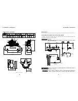
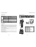
AIR DISTRIBUTION NETWORK TYPICAL INSTALLATION DIAGRAM
This diagram is only a guide to a typical air system. Your needs may be different and you should consult a professional for
more information regarding your particular installation.
DANGER
!
IMPORTANT
Follow all safety precautions and warnings always turn off and lockout/tagout the main power
supply before serviving unit.
DANGER
!
CAUTION
!
To remove moisture from air line, the main feeder line must run downhill to drain-leg at a
rate of 3/4
”
to 1
”
every 10
’
.
Recommended pipe and fittings: black iron pipe no smaller than tank outlet size (NPT). For
systems over 100 feet in length increase by one pipe size or loop air lines back to receiver.
Air flow
Feeder line
By-pass
By-pass
Air flow
Line
filter
Air dryer or
aftercooler
Drain-leg
Moisture
trap with
drain
Non-lubricated
supply line
Air hose
to air tool
Quick coupler
Regulator
with gauge
Lubricator
CAUTION:
Never use for
spraying or
similar
applications.
Main disconnect
(ON-OFF)
Flexible
air-line
1/2
”
until 2
”
turn
shut-off valve
Air/water
filter with
petcock
Disp tee
with drain
1/4
”
Turn
shut-off
valve
Power painel
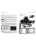
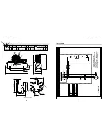
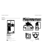
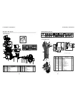
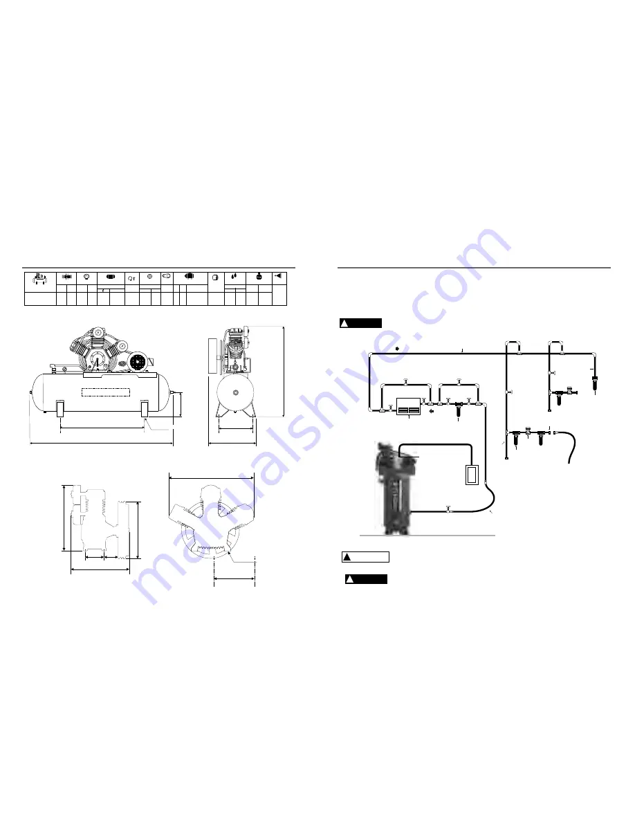
TECHNICAL DATA 10120HW40X
397
Black
(pump)
Gray
(tank)
1,500
ELECTRIC MOTOR
OIL CAP.
WEIGHT WITH MOTOR
DISCHARGE
SIZE
BELT
SIZE
COLOR
REF.
Volume
ml
Kg
2P
2P
VOLTAGE V
[ ]
hp
kW
10120HW40X
105
2-B
1
’’
MODEL
Ø PULLEY
rpm
710
4.1
inches
mm
40 1,132 175
12
DISPLACEMENT MAX. PRESSURE
cfm
psig
bar
Geom. Volume
l/min
427
113
TANK
gal
878
lbs
in qt.
1,580
10
Three-phase
208/230/460
7.5
51.2/1,300
18.9/480
12.6/320
21.6/550
8.6/218 4.7/120
Ø 19.7/500
24.4/620
28.7/730
78.3/1,990
13.3/340
Ø 0.55/14
47.3/1,200
1'' BSP
4 x Ø 5/8 /16
29.0/740
Note: dimensions in inch/mm.


