AIR COMPRESSOR - OWNER'S MANUAL
13
AIR COMPRESSOR - OWNER'S MANUAL
36
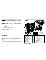
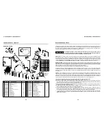
BREAK-IN PROCEDURES
4.
After eight hours of running, check the oil level and look for any oil leaks. Turn the compressor off and bleed down the
tank pressure to about 20 psi and open the drain valve to allow all of the moisture to drain from the tank. Allow the pump to
cool and torque the head bolts and the bolts which hold the inner and after cooler.
5.
6.
We recommend that you change your oil after the first 8 hours of operation. This could help remove any small particles in
the pump and will improve the life of the pump.
After the first week of operation follow the guidelines in the MAINTENANCE SCHEDULE.
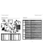
MAINTENANCE SCHEDULE
THE LIFE OF YOUR COMPRESSOR WILL BE DETERMINED BY HOW IT IS MAINTAINED.
- A clean pump will run cooler, causing less moisture in the tank and lines. Since the cooler the air is, the easier it is to
compress, cleaning of the pump will make the motor and pump run less and save you money.
- A clean air filter will allow you to compress more air per ciyle. A dirty air filter causes the oil from the crankcase to be
sucked up pas the piston rings if happens you get MAJOR problems. First, the oil gets into your air system, mixes with
the water vapor in the lines and creates a
“
mayonnaise
”
that can foul up tools and destroy paint systems with
“
fish
eye
”
. Secondly, the oil becomes baked onto the valve plates where it builds up and cuts the efficiency of the pump
dramatically.
- Clean oil at the proper level in the crankcase is your best insurance against pump failure.
- A dry tank will last many more years than a tank with water sitting in it rusting away metal. The tank is a great heat sink
and will take out the bulk the moisture that is in your air system
.
t
if you drain it
WARNING
DAILY
WEEKLY
MONTHLY
Turn off power before servicing and be sure the air tank is unloaded. These instructions are based on normal operating
conditions. If the compressor is located in an exceedingly dusty area, increase the frequency of all inspections.
- Inspect the compressor visually.
- Check oil level and add some if necessary, before turning the compressor on.
- Drain moisture from the piping system.
- Be sure there is no excessive or unusual vibration or noise.
- Remove and clean intake air filters; do not wash the filter element.
- Check V-belt for tightness. Belt tension should be adjusted to allow approximately 3/8" to 1/2" (9 to 13 mm) deflection with
normal thumb pressure, see Figure page 16.
- Clean cylinders externally, cylinder head, motor, fan blade, tubing, and tank.
- ASME safety valve should be tested manually to see if it is working properly.
- Check entire system for air leakage around fittings, etc by using water and soap lather.
- Check the pressure switch operation.
- Check for oil contamination and change it if necessary.
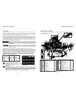
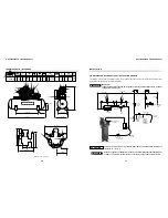
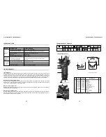
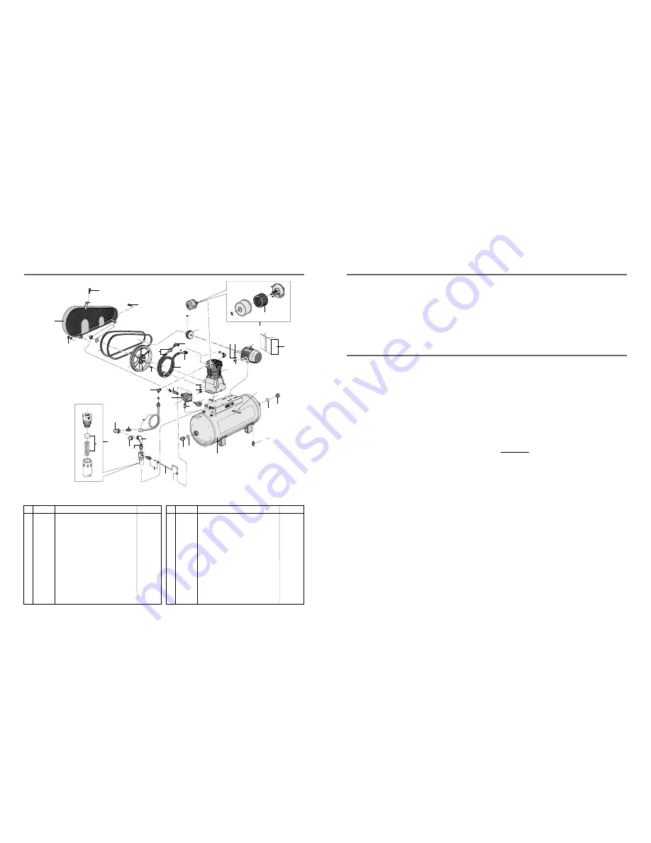
TECHNICAL DATA 10120HL40X
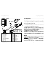
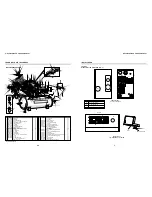
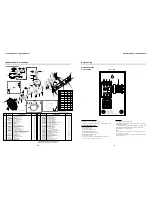
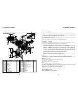
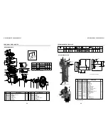
AIR COMPRESSOR PARTS
38
37
36
29
35 23
28
24
13
18
19
16
15
13
12
11
14
7
6
44
20
21
35
34
6
24
3
24
1
2
24
3/8 x 1.1/4 hex head bolt
Bare pump
1/4 ASME safety valve
Pressure gauge
Strain relief
Motor 208/230/460V (three-phase)
Pulley
Start switch**
Support start switch**
Start switch pressure switch cord (not shown)**
Motor start switch cord (not shown)**
3/8 x 1.1/2 hex head bolt
3/8 lock washer
3/8 x 1/2 Allen hex without head
Air filter
Filter element
3/4 plug
3/4 side elbow
BSP 90 3/4 elbow
NPT 3/4 x 3/4 straight connection
1/4 nipple
Hose for tank drain (not shown)
º
CODE
QTY
DENOMINATION
04
01
01
01
01
01
01
01
01
01
01
04
08
01
01
01
01
01
01
02
01
01
No.
23
24
25
26
27
28
29
30
31
32
33
34
35
36
37
38
39
41
42
43
44
45
4
Belt guard
1/4 hex nut
Belt
Intercooler
NPT 3/4 straight connection
BSP 3/4 elbow
Aftercooler
Check valve
Check valve kit
NPT 1/8 x 1/4 elbow
1/4 Tube
2 Plug
O ring
Pressure switch
120 gal horiz. tank
1/4 tank drain valve
3/4 Nipple
2 x 1 Reduction bushing
Motor fastening plate
3/8 hex nut
1/4 x 3/4 hex head bolt
3/8 Washer
CODE
QTY
DENOMINATION
830.1208-0
*
004.0128-0
709.1663-0
21011002
003.0151-5
709.1667-0
60281501
34004508
003.0005-5
709.1669-0
003.0514-0
023.0339-0
012.0845-0
25003832A
022.0206-0
003.0036-5
003.0512-0
21028503
*
*
*
01
02
02
01
03
03
01
01
01
01
01
01
02
01
01
01
01
01
02
04
02
08
No.
1
2
3
4
5
6
7
8
9
10
11
12
13
14
15
16
17
18
19
20
21
22
*
932.9324-0
022.0057-0
011.0118-0
012.0723-0
015.0602-0
709.1612-0
012.0937-0
701.0379-0
012.0907-0
012.0908-0
*
*
*
809.1086-0
007.0118-0
003.0031-4
003.0343-0
003.0151-5
21011002
003.0033-0
709.1246-0
* Part available in the market - not sold by Schulz. ** Optional start switch
30
22
5
24
24
27
22
10
39
17
41
42
43
21
14
26
9
8
25
31
45


