16
AIR COMPRESSOR - OWNER'S MANUAL
AIR COMPRESSOR - OWNER'S MANUAL
33
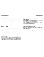
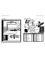
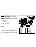
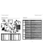
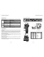
PULLEY ALIGNMENT -
Three examples of pulley misalignment are shown below. To check the pulley alignment, remove
the beltguard and place a straight edge against the pump flywheel. Measure the distance from the straight edge to the
motor pulley at several points. If the pulley needs to be adjusted, follow the procedure below.
1. Loosen the motor mounting bolts.
2. Loosen the setscrews on the motor pulley.
3. Align the motor pulley using the straight adge as a guide.
4. Retighten the motor pulley setscrew using thread-looking fluid.
5. Adjust the belt tension as described previously.
6. Retighten the motor mounting bolts.
7. Replace the belt guard and test.
STRAIGHTEDGE
PUMP
FLYWHEEL
DRIVE
BELT
EDGE
DRIVE
BELT
EDGE
MOTOR
PULLEY
A
B
C
Do not operate the compressor with any of its safety guards, shields, or screens removed.
Never cause the compressor to run at speeds in excess of the factory set RPM. Always follow
all safety precautions and warnings when performing service.
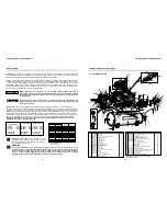
BELT TENSION -
Proper belt tension and pulley alignment must be maintained for maximum drive efficiency and belt life.
The correct tension exists if a deflection of 1/2
”
occurs by placing 10 pounds of force midway between the motor pulley and
the pump flywheel. See figure below. This deflection can be adjusted using the following procedure.
1. Remove belt guard.
2. Loosen the motor mounting bolts. Remove belts.
3. Shift the motor to the point where the correct tension
exists.
4. Retighten motor mounting bolts. Replace belts.
5. Check the tension again.
6. Replace the belt guard.
x = 1/2'' deflection
10 lb force
x
MAINTENANCE SCHEDULE
ANGULAR MISALIGNMENT
PARALLEL MISALIGNMENT
WARNING
!
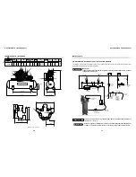
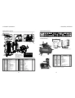
TECHNICAL DATA 7.580HV30X
Compressor dimension (inch/mm)
Height = 42.7/1,085, lenght = 55/1,400, width = 25.2 / 640
230
Black
(pump)
Gray
(tank)
230
0,880
ELECTRIC MOTOR
OIL CAP.
WEIGHT WITH MOTOR
DISCHARGE
SIZE
BELT
SIZE
COLOR
REF.
Volume
ml
Kg
Single-phase
VOLTAGE V]
[
hp
kW
7.580HV30X
226
1/2
’’
MODEL
Ø PULLEY
rpm
960
9.0
inches
mm
30
850
175
12
DISPLACEMENT MAX. PRESSURE
cfm
psig
bar
Geom. Volume
l/min
300
80
TANK
gal
508
lbs
in qt.
0,920
7.5
Three-phase
208/230/460
5.6
1
2
12 - 13
14 - 15
18
21
7
19
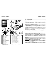
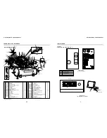
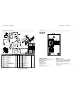
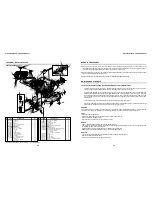
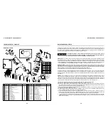
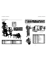
AIR COMPRESSOR PARTS
115
4.5
Bare pump
Belt guard
Aftercooller
Pressure switch
Pressure gauge
1/4 tube
Check valve
1/4 ASME safety valve
80 gal vertical tank
1/4 tank drain valve
Hose for tank drain (not shown)
Motor 208/230/460V 2P
Motor 230V 4P
Pulley 4P
Pulley 2P
Belt
3/8 x 1.1/2 hex head
3/8 x 1.1/4 hex head
3/8 hex nut
1/4 niple
Motor fastening plate
CODE
single-phase
Q
TY
DENOMINATION
-
830.1222-0
709.1228-0
012.0845-0
011.0114-0
709.1679-0
022.0213-0
022.0162-0
25003837
022.0206-0
709.1246-0
-
015.0616-0
709.0928-0
-
004.0125-0
*
*
*
003.0174-4
21028503
01
01
01
01
01
01
01
01
01
01
01
01
01
01
01
02
04
04
04
01
02
No.
1
2
3
4
5
6
7
8
9
10
11
12
13
14
15
16
17
18
19
20
21
CODE
three-phase
-
830.1222-0
709.1228-0
012.0845-0
011.0114-0
709.1679-0
022.0213-0
022.0162-0
25003837
022.0206-0
709.1246-0
015.0583-0
-
709.1426-0
709.1661-0
004.0110-0
*
*
*
003.0174-4
21028503
* Part available in the market - not sold by Schulz.
16
3
4
9
6
5
8 20
17
2-A
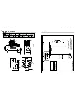
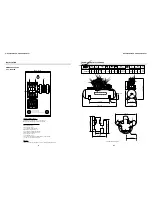
Note: dimensions in inch/mm.
580/22.8
Ø 10.5/0.41
410/16.1
200/7.9
420/16.5
220/8.7
75/3.0
435/17.1
4 x 5/8 x 27.5 / 700 x 18.9
Ø
10
11

