35
3.
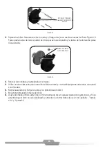
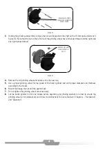
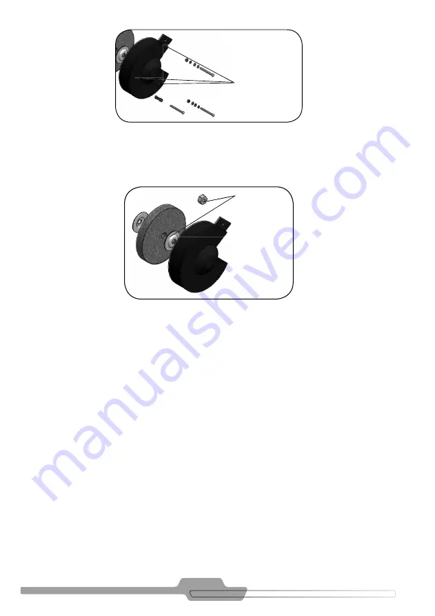
Holding the grinding wheel fi rmly, remove the nut and fl ange from the shaft with a 19-mm open end wrench.
Figure 9.3. Note that the nut on the left side of the grinding wheel has left-handed thread and the right side
has right-handed thread;
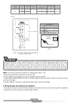
FIGURE 9.2
4.
Remove the old grinding wheel and replace it by the new one;
5.
Use a proper grinding wheel for the speed of the bench grinder and with proper diameter and thickness
according to the model;
6.
Mount the fl ange, the nut and the guards back;
7.
Do not tighten the grinding wheel nut excessively;
8.
Let the bench grinder run for one minute before beginning any grinding operation in order to ensure the
grinding wheel is not unbalanced, and follow the instructions for use contained in Chapters – “Installation”
and “Operation”.
FIGURE 9.3
REMOVE MOUNTING
SCREWS FROM GRINDING
WHEEL GUARD
REMOVE NUT AND
FLANGE FROM THE
SHAFT


