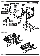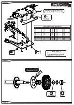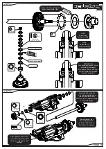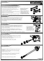
Apply a thin layer of silicone
grease covering this face.
1/4”x 5/16” x 0.10mm
x 2
1/4”x3/8”
x 2
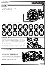
Tire Size (mm) Ride Height (mm) Caster Spacer A (mm) Spacer B (mm)
39.5
3.0
3°
0.0
0.0
41.5
3.0
3°
1.0
1.0
43.5
3.0
3°
2.0
2.0
39.5
3.0
4°
0.0
0.5
41.5
3.0
4°
1.0
1.5
43.5
3.0
4°
2.0
2.5
39.5
3.0
5°
0.0
1.0
41.5
3.0
5°
1.0
2.0
43.5
3.0
5°
2.0
3.0
Ride Height and Caster Chart
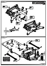
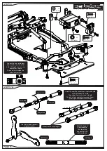
Adjusting the spacers under the
beam sets ride height and caster.
SPEED SECRETS
For quicker and easier adjustments see
U7943 Alloy Spacer Clip 0.50mm and
U7944 Alloy Spacer Clip 0.75mm
Spacer B
Spacer A
M3 x 8
x 2
M3 x 6
x 2
2mm Silver Ride
Height Spacer
x 4
1 / 1 2 t h P R O L M P C H A S S I S
STEP 13
STEP 12
PAGE 9


