background image

Maintenance 


38 

01.00|1416054_ROTA-M2 + 2 |en 


Maintenance 


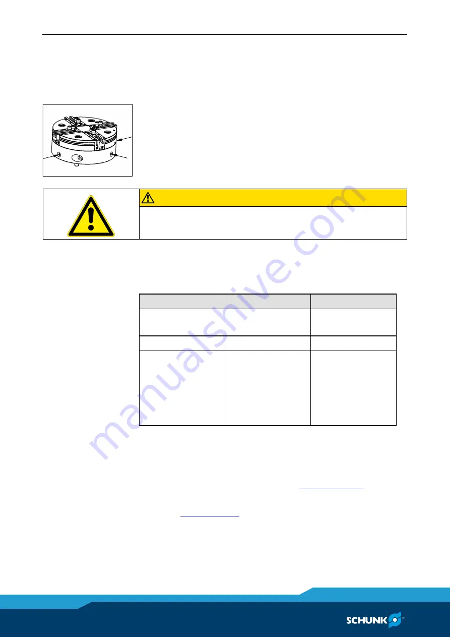
Lubrication 

To maintain the safe function and high quality of the lathe chuck, it 

has to be regularly lubricated at the lubrication nipples in the 

chuck body. 
The lathe chuck must be lubricated in the open position. 
For optimum grease distribution, the chuck piston must travel 

through the entire stroke several times after lubrication. 


CAUTION 

Allergic reactions due to grease in contact with skin! 

Wear gloves. 


Maintenance intervals 

Lubricating the greasing areas:


Lubrication interval  Demands 

To be carried out 

every 25 hours 

normal / use of 

coolant 

User 

every 8 hours 

high / use of coolant  User 

after 1200 hours or 

when needed 

Full cleaning with 

disassembly of lathe 

chuck depending on 

type of 

contamination and 

quantity 

Specialist personnel 


Disassembling and assembling the chuck 

The item numbers specified for the corresponding individual 

components relate to chapter drawings.

(

 12, Page 48)


The stationary chuck can only be disassembled once it has been 

removed.


(

 5, Page 29)


1  Loosen the screws of the T-nuts and remove T-nuts with top 

jaws. 

2  Loosen screws (item 30) and lift the lathe chuck from the 

machine spindle with lifting equipment. 

7.1 


7.2 

7.3 

Summary of Contents for 1389670

Page 1: ...Translation of Original Operating Manual Manual Lathe Chucks ROTA M flex 2 2 Assembly and Operating Manual Superior Clamping and Gripping...

Page 2: ...for the purpose of technical improvement Document number 1416054 Version 01 00 23 04 2020 en H D SCHUNK GmbH Co All rights reserved Dear Customer thank you for trusting our products and our family own...

Page 3: ...13 2 11 Malfunctions 13 2 12 Disposal 13 2 13 Fundamental dangers 14 2 13 1 Protection during handling and assembly 14 2 13 2 Protection during commissioning and operation 14 2 13 3 Protection agains...

Page 4: ...mounting 33 6 Function 34 6 1 Function and handling 34 6 2 Function test before use 34 6 3 Replacement or renewal of jaws 35 6 4 Clamping the workpiece 36 6 5 Compensation workpiece dimensions 37 7 Ma...

Page 5: ...trations in this manual are provided for basic understanding and may differ from the actual product design In addition to these instructions the documents listed under 1 1 2 Page 6 are applicable Pres...

Page 6: ...llowing conditions Observe the applicable documents 1 1 2 Page 6 Observe the ambient conditions and operating conditions 2 6 Page 10 Observance of the specified care and maintenance instructions 7 Pag...

Page 7: ...of rotation and the clamping force of the lathe chuck must be determined by the operator for the respective clamping task however the technical data engraved on the lathe chuck should never be exceed...

Page 8: ...of concentration Clamping of insufficiently rigid workpieces clamping of workpieces that do not meet the specifications The rigidity of the workpiece is not sufficient to provide the lathe chuck with...

Page 9: ...clamping points at a greater distance lead to greater surface pressure in the jaw guidance and can significantly reduce the clamping force If for constructional reasons the special chuck jaws are hea...

Page 10: ...fety data sheet for LINOMAX plus available at www schunk com Required ambient conditions and operating conditions Incorrect ambient and operating conditions can make the product unsafe leading to the...

Page 11: ...he user has been instructed by the operator regarding the tasks entrusted to them and the potential dangers of inappropriate behavior The user may only carry out tasks that go beyond the use in normal...

Page 12: ...protective gloves and safety goggles when handling hazardous substances Wear close fitting protective clothing and also wear long hair in a hairnet when dealing with moving components Notes on safe o...

Page 13: ...ions Immediately remove the product from operation and report the malfunction to the responsible departments persons Order appropriately trained personnel to rectify the malfunction Do not recommissio...

Page 14: ...siderable material damage Have all work carried out by appropriately qualified personnel For all work secure the product against accidental operation Observe the relevant accident prevention rules Use...

Page 15: ...avoid accidents and or material damage human access to the movement range of the machine must be restricted Limit prevent accidental access for people in this area due through technical safety measure...

Page 16: ...g or hair being caught on the lathe chuck and being dragged into the machine Loose clothing or long hair may become caught on projecting parts of the lathe chuck and be drawn into the machine The mach...

Page 17: ...jaws on workpiece If an incorrect clamping position is chosen for the chuck jaws on workpiece the base and top jaws may become damaged The T nuts for connecting the top jaws to the base jaws must not...

Page 18: ...al torque of base jaw kgm McGB 0 08 0 11 0 262 0 577 0 925 Spindle holder ISO 702 4 No 8 220 H6 No 11 300 H6 No 15 380 H6 No 15 380 H6 No 15 380 H6 Operating temperature 15 C to 60 C Ensure minimal we...

Page 19: ...Torques per screw 01 00 1416054_ROTA M2 2 en 19 Dimensions 3 2...

Page 20: ...24 M24 M24 K mm 28 28 31 31 31 L mm 5 5 6 6 6 M mm 63 5 63 5 83 94 94 N mm transport M8 M8 M12 M16 M16 O 45 45 45 45 45 P mm 20 5 19 5 20 5 19 5 25 26 26 26 Q mm 11 10 11 10 13 5 13 5 14 5 14 5 R1 min...

Page 21: ...ter of the lathe chuck The lathe chuck is in perfect condition and lubricated with SCHUNK LINOMAX plus special grease If one or more of these prerequisites is modified the graphs will no longer be val...

Page 22: ...Torques per screw 22 01 00 1416054_ROTA M2 2 en Clamping force RPM graph for ROTA M flex 2 2 315 Clamping force RPM graph for ROTA M flex 2 2 400 Clamping force RPM graph for ROTA M flex 2 2 500...

Page 23: ...e top jaw kg ssp Safety factor for clamping force mB Mass of chuck jaw set kg sz Safety factor for machining Mc Centrifugal torque kgm s Max clamping force of lathe chuck N kgm 9 81 Nm Calculation of...

Page 24: ...clamping force Fspmin Consequently the workpiece is released spontaneously Do not exceed the calculated RPM Do not fall below the necessary minimum clamping force Reduction in effective clamping force...

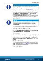
Page 25: ...and the speed of rotation CAUTION For safety reasons in accordance with DIN EN 1550 the centrifugal force may be a maximum of 67 of the initial clamping force The formula for the calculation of the to...

Page 26: ...of top jaw rsAB 0 107 m application specific Safety factor Sz 1 5 according to VDI 3106 Safety factor Ssp 1 5 according to VDI 3106 Note Masses of the jaw mounting screws and T nuts are not taken int...

Page 27: ...shutdown CAUTION For safety reasons the calculated permissible RPM may not exceed the maximum RPM inscribed on the lathe chuck Example of calculation Permissible RPM for a given effective clamping for...

Page 28: ...g achieved see DIN EN 1550 6 2 e This applies particularly to high speeds asymmetrical workpieces or the use of various top jaws as well as uneven application of lubricants In order to prevent damage...

Page 29: ...g Make sure that no residual energy remains in the system CAUTION Danger of injury due to sharp edges and rough or slippery surfaces Wear personal protective equipment particularly protective gloves 1...

Page 30: ...and radial run out accuracy using a dial indicator The concentricity error of the locating centering of the mount must not exceed 0 005 mm and the maximum axial run out error of the contact surfaces...

Page 31: ...included in the scope of delivery CAUTION When mounting with the intermediate flange never allow the outer rim of the lathe chuck body to make contact The flange must support on the entire surface Lat...

Page 32: ...mbly preparation for lathe chuck with reduction or expansion adapter plate If the bolt pitch circle of the machine spindle does not correspond to the bolt pitch circle of the lathe chuck a reduction o...

Page 33: ...mount must be used Fasten the direct mount to the lathe chuck prior to lathe chuck assembly 1 Before mounting the direct mount on the cylindrical recess of the lathe chuck remove dirt or chips from t...

Page 34: ...mount standard jaws as well as special jaws for complicated workpiece shapes The top jaws are moved or changed in the open clamping position WARNING Clamping further above the lathe chuck surface res...

Page 35: ...top jaws the serration has to be cleaned and greased with SCHUNK LINOMAX plus special grease Tighten the jaw mounting screws screw grade 12 9 to the specified torque 4 Page 28 CAUTION Tighten the moun...

Page 36: ...must be completely recessed only then is permissible clamping achieved WARNING When a workpiece is clamped the indicator pins must be completely recessed If the indicator pins are not completely rece...

Page 37: ...lso the area within which the indicator pins are completely recessed Using the compensation function the lathe chuck can accommodate workpieces that have the dimension X compensation per jaw when thei...

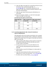
Page 38: ...greasing areas Lubrication interval Demands To be carried out every 25 hours normal use of coolant User every 8 hours high use of coolant User after 1200 hours or when needed Full cleaning with disas...

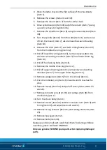
Page 39: ...er drive ring item 13 11 Pull off four locking bolts item 15 12 Remove the middle drive ring item 12 13 Pull off upper drive ring item 11 remove two connecting members item 7 from upper drive ring ite...

Page 40: ...d 24 CAUTION Use the cover plates item 23 on guideways 1 and 4 6 Fix the cover plates items 23 and 24 with screws item 34 7 Press projecting O ring sections item 26 into the gap between the chuck body...

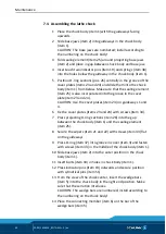
Page 41: ...eeves item 14 into the lower drive ring item 13 chamfers must point downwards 22 Insert the locking bolts item 15 into the bores of the drive rings 23 Insert the slide item 17 in the sliding block ite...

Page 42: ...unt item 7 to the chuck body with screws items 31 and 32 34 Turn the lathe chuck 35 Loosen screws item 34 and fix cover plate items 23 and 24 against the mount item 7 tighten the screws item 34 CAUTIO...

Page 43: ...s switched during assembly Disassemble lathe chuck and assemble using correct component allocation Top jaws not correctly turned ground Repeat turning grinding Dirty clamping faces Cleaning the clampi...

Page 44: ...n Adjust position of top jaws to workpiece geometry Imbalance due to workpiece Compensate for imbalance by adding weight to the chuck body Imbalance due to top jaw Correct the top jaw position Imbalan...

Page 45: ...the nominal clamping force the lathe chuck must be dismantled cleaned and relubricated Disposal After decommissioning place the chuck in a position that enables any liquids in the lathe chuck to drain...

Page 46: ...haracterization Quantity 1 Chuck body 1 2 Base jaws 4 3 Cover 1 5 Wedge bar 4 6 Connecting member 4 7 Mount 1 8 Spindle 1 9 Spindle nut 1 10 Seat of bearing 1 11 Drive ring top 1 12 Drive ring middle...

Page 47: ...ring 1 37 O ring 1 38 Compression spring 2 41 T nut SV90 SV60 8 4 47 Actuation keys 1 48 Cylindrical pin 2 49 Assembly key 1 50 Eye bolt 1 Accessories and replacement orders at H D SCHUNK GmbH Co Spa...

Page 48: ...Drawing 48 01 00 1416054_ROTA M2 2 en Drawing 12...

Page 49: ...of the machine into which the partly completed machine is to be installed with the provisions of the Machinery Directive 2006 42 EC is confirmed Applied harmonized standards especially DIN EN ISO 1210...

Page 50: ...1 2 1 Safety and reliability of control systems X 1 2 2 Control devices X 1 2 3 Starting X 1 2 4 Stopping X 1 2 4 1 Normal stop X 1 2 4 2 Operational stop X 1 2 4 3 Emergency stop X 1 2 4 4 Assembly o...

Page 51: ...1 2 Warning devices X 1 7 2 Warning of residual risks X 1 7 3 Marking of machinery X 1 7 4 Instructions X 1 7 4 1 General principles for the drafting of instructions X 1 7 4 2 Contents of the instruct...

Reviews: