13
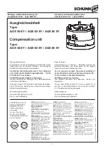
Montage- und Betriebsanleitung für
Ausgleichseinheit
Type AGE-XY
Assembly and Operating Manual for
Compensation unit
Type AGE-XY
10.
Zubehör
(auf besondere Bestellung)
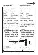
10.1 Näherungsschalter
(Elektronische Magnetschalter)
Technische Daten:
Spannung:
10 – 30 V DC
Restwelligkeit:
≤
15%
Schaltstrom max.:
200 mA, kurzschlussfest
Schalthysterese:
≤
15% vom Nennschaltabstand
Temperaturbereich:
– 10°C bis + 70°C
Schaltfrequenz max.:
1000 Hz
Spannungsabfall ca.:
1.5 V
Schutzart nach DIN EN 60529: IP 67*
* für die Rundsteckverbindung nur im verschraubten Zustand
HINWEIS:
Die Näherungsschalter sind Zubehör und müssen gesondert
bestellt werden.
Achten
Sie
auf
einen
sachgemäßen
Umgang
mit
den
Näherungsschalter:
–
Ziehen Sie die Befestigungsschraube nicht übermäßig fest
an.
–
Zulässiger Biegeradius des Kabels = 15 x Kabeldurchmesser.
–
Vermeiden Sie Kontakt der Näherungsschalter zu harten
Gegenständen,
sowie
zu
Chemikalien,
insbesondere
Salpeter-, Chrom- und Schwefelsäure.
Die eingesetzten Näherungsschalter sind verpolungsgeschützt
und kurzschlussfest.
ACHTUNG!
Die Näherungsschalter sind elektronische Bauteile,
welche empfindlich auf hochfrequente Störungen
oder elektromagnetische Felder reagieren können.
Prüfen Sie die Anbringung und Installation des
Kabels. Der Abstand zu hochfrequenten Störquellen
und deren Zuleitung muss ausreichend sein.
Das Parallelschalten mehrerer Sensorausgänge der
gleichen Bauart ist zwar erlaubt, erhöht aber nicht
den zulässigen Laststrom. Beachten Sie weiterhin,
dass sich der Leckstrom der einzelnen Sensoren
(ca. 2 mA) addiert.
10.
Accessories
(on separate order)
10.1 Proximity switch
(Electronic solenoid switch)
Technical data:
Supply voltage:
10 – 30 V DC
Operation voltage:
≤
15%
Max. load current:
200 mA, short-circuit-proof
Hysteresis:
≤
15% of nominal sensing distance
Range of operat. temp.:
– 10°C to + 70°C
Max. operating frequency:
1000 Hz
Voltage drop, approx.:
1.5 V
Protect. class DIN EN 60529: IP 67*
* For concentric plug and socket only if assembled
NOTE:
Proximity switches are accessories and have to be ordered sepa-
rately.
Make sure that the proximity switches are handled properly:
–
Do not tighten the fastening screw too strongly.
–
Admissible bending radius of the cable = 15 x cable diameter.
–
Do not allow the proximity switch to contact hard objects or
chemicals, especially nitric, chromic and sulphuric acid.
The inductive proximity switches used are short-circuit-proof and
have reverse voltage protection.
CAUTION!
The inductive proximity switches are electronic com-
ponents which can react sensitively to high-frequen-
cy interference or electromagnetic fields. Check the
attachment and installation of the cable. The distan-
ce to high-frequency sources of interference and
their feed lines must be sufficiently great.
Connecting several sensor outputs of the same type
(npn, pnp) in parallel is allowed, but this does not
increase the permissible load current. Moreover,
please note that the leakage current of the individual
sensors (approx. 2 mA) must be added together.
22
39.
2
3.
1
ca
.
/ approx
.
3
00
M
2
3
.9
M
8
x
1
Ø
9
.
5
Schaltfunktion: in unbedämpftem Zustand gezeichnet
Output: drawn in non-actuated condition
Type
Schaltfunktion / Output
Ident-Nr. / Id.-No.
INS 22
Schließer / Closer
301 523

