14
Montage- und Betriebsanleitung für
Ausgleichseinheit
Type AGE-XY
Assembly and Operating Manual for
Compensation unit
Type AGE-XY
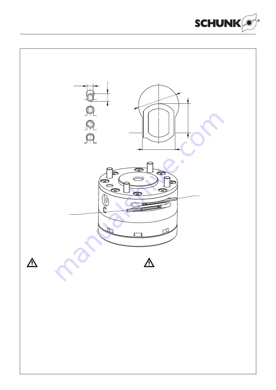
ACHTUNG!
Das max. Anzugsmoment der Näherungsschalter-
Schraube beträgt 15 Ncm.
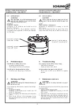
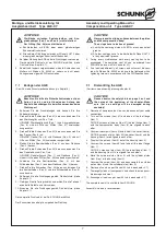
Ausgleichseinheit »verriegelt«:
1.
Verriegeln Sie die AGE, indem Sie den Anschluss
B
mit
Druck beaufschlagen.
2.
Schieben Sie den Magnetschalter
1
in die Profilnut bis dieser
schaltet.
3.
Fixieren Sie den Magnetschalter
1
in dieser Stellung mit der
Schraube im Magnetschalter.
4.
Testen Sie die Funktion, indem Sie die AGE entriegeln und
verriegeln.
Ausgleichseinheit »entriegeln«:
1.
Entriegeln Sie die AGE, indem Sie den Anschluss
A
mit
Druck beaufschlagen.
2.
Schieben Sie den Magnetschalter
2
in die Profilnut bis dieser
schaltet.
3.
Fixieren Sie den Magnetschalter
2
in dieser Stellung mit der
Schraube im Magnetschalter.
4.
Testen Sie die Funktion, indem Sie die AGE verriegeln und
entriegeln.
CAUTION!
The maximum starting torque of the proximity switch
screw is 15 Ncm.
”Locking” of the compensation unit:
1.
Lock the AGE unit by actuating connection
B
with compres-
sed air.
2.
Move the solenoid switch
1
into the groove of the profile until
it switches.
3.
Locate the solenoid switch
1
in this position with the screw
inside the solenoid switch.
4.
Control proper function by unlocking and locking the AGE
unit.
”Unlocking” of the compensation unit:
1.
Unlock the AGE unit by actuating connection
A
with compres-
sed air.
2.
Move the solenoid switch
2
into the groove of the profile until
it switches.
3.
Locate the solenoid switch
2
in this position with the screw
inside the solenoid switch.
4.
Control proper function by locking and unlocking the AGE
unit.
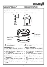
Magnetschalter
2
»entriegelter Zustand«
Solenoid switch
2
“unlocked condition”
Magnetschalter
1
»verriegelter Zustand«
Solenoid switch
1
“locked condition”
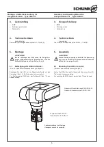
Montage und Einstellung der elektronischen
Magnetschalter
Montageschritte zur Befestigung der Näherungsschalter
Assembly and adjustment of electronic solenoid
switches
How to fasten the proximity switches
3.1
3
.
9
2
.
5
-
2
.
8
3.
4
– 0
– 0
.1
Ø
4
.1
±
0
.1

