background image

Maintenance

24

03.00 | AGE-F-XY | Assembly and Operating Manual | en | 389002

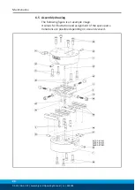
6.5 Assembly drawing

The following figure is an example image. 
It serves for illustration and assignment of the spare parts.
Variations are possible depending on size and variant.

Summary of Contents for AGE-F-XY Series

Page 1: ...Original Operating Manual Assembly and Operating Manual AGE F XY Compensation unit with spring return...

Page 2: ...erations for the purpose of technical improvement Document number 389002 Version 03 00 24 06 2019 en SCHUNK GmbH Co KG All rights reserved Dear Customer thank you for trusting our products and our fam...

Page 3: ...Notes on safe operation 9 2 9 Transport 9 2 10 Malfunctions 10 2 11 Disposal 10 2 12 Fundamental dangers 10 2 12 1 Protection during commissioning and operation 11 2 12 2 Protection during handling a...

Page 4: ...sembly and Operating Manual en 389002 6 Maintenance 22 6 1 Maintenance interval 22 6 2 Lubricants Lubrication points basic lubrication 22 6 3 Disassemble the module 22 6 4 Maintaining and assembling t...

Page 5: ...is manual Illustrations in this manual are provided for basic understanding and may differ from the actual product design In addition to these instructions the documents listed under Applicable docume...

Page 6: ...ent conditions and operating conditions Parts touching the workpiece and wear parts are not included in the warranty 1 3 Scope of delivery The scope of delivery includes Compensation unit AGE F XY in...

Page 7: ...ine system The applicable guidelines must be observed and complied with The product is intended for industrial and industry oriented use Appropriate use of the product includes compliance with all ins...

Page 8: ...e All work may only be performed by qualified personnel Before working with the product the personnel must have read and understood the complete assembly and operating manual Observe the national safe...

Page 9: ...t handling of the personnel Incorrect handling and assembly may impair the product s safety and cause serious injuries and considerable material damage Avoid any manner of working that may interfere w...

Page 10: ...fety devices Before commissioning the product take appropriate protective measures to secure the danger zone Disconnect power sources before installation modification maintenance or calibration Ensure...

Page 11: ...ve measures to secure the danger zone Never step into the danger zone during operation 2 12 2 Protection during handling and assembly Incorrect handling and assembly Incorrect handling and assembly ma...

Page 12: ...yload load capacity F pull N 100 200 300 2800 Max payload load capacity F pressure N 200 500 3000 12000 Weight kg 0 123 0 23 0 78 3 13 Max reset force N Version 1 Version 2 Version 3 3 5 5 5 7 0 5 0 7...

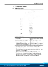
Page 13: ...customer 4 AGE F XY compensation element 5 Handling device e g gripper 6 Mounting screws for gripper An interface plate with a hole pattern for locating holes is optionally available The adapter plate...

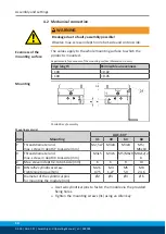
Page 14: ...ible unevenness 100 0 02 100 0 05 Mounting Possibilities of assembly Mounting material Item Mounting AGE F XY 31 40 63 80 Y Thread diameter and max screw in depth Y tool side mm M2 5x7 M3x8 M4x8 M5 M6...

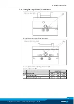
Page 15: ...002 15 4 3 Setting the stop in order to limit stroke Set screw 52 to limit stroke for type AGE F XY 40 Set screw 52 to limit stroke for types AGE F XY 63 80 Dimensions of set screw 52 Item Designation...

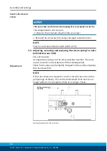
Page 16: ...ting removing and replacing the return spring for units built before June 2016 The unit contains 4 compression springs for the return position function The units are set ex works in accordance with th...

Page 17: ...2 0 2 18 5 0 2 Setting dimension for Version 3 mm 9 3 0 2 12 5 0 2 15 2 0 2 18 5 0 2 The catalog values have been ascertained in this basic setting Removing Replacing Position of the item numbers Ass...

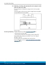
Page 18: ...on the unit can not be changed anymore applies to units delivered since June 2016 Replacing springs Removing Replacing Position of the item numbers Assembly drawing 24 Remove the set screws 50 Remove...

Page 19: ...sitions of the sensor For example Adapter plate made of ordinary steel At ferromagnetic adapter plates First mount the product on the adapter plate Then set the position of the magnetic switch NOTE Do...

Page 20: ...on of the magnetic switch MMS stop position A The magnetic switches MMS are mounted and adjusted equally for each axis movement Assembly steps Screw in the sensor OR insert the sensor axially into the...

Page 21: ...pring adjustment screwed in too far Turn back the setscrew 50 Adjusting removing and replacing the return spring for units built before June 2016 16 5 2 Magnetic switch MMS does not work cannot be adj...

Page 22: ...exroth Dynalub 510 6 3 Disassemble the module Position of the item numbersAssembly drawing 24 Detach the module from the handling device Disconnect the cable connection Undo setscrews 51 52 on the bot...

Page 23: ...s 6 4 Maintaining and assembling the module Maintenance Clean all parts thoroughly and check for damage and wear Treat all greased areas with lubricant Lubricants Lubrication points basic lubrication...

Page 24: ...E F XY Assembly and Operating Manual en 389002 6 5 Assembly drawing The following figure is an example image It serves for illustration and assignment of the spare parts Variations are possible depend...

Reviews: