Assembly and Operating Manual
AGE-F-XY
– Compensation Unit with spring return
17
Date printed 28.12.2009
Installation of sensor
Setting up the switching points (automatic mode)
-
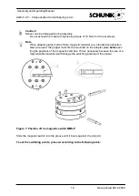
Turn in the sensor as illustrated on picture 1 to 4.
OR
Operation
Information
-
Push the sensor axially into the slot until it con-
tacts the stop (many SCHUNK products are
equipped correspondingly)
1. Keep the button
(Item /2/) pressed for 2
seconds.
after 2 seconds LED 1
(item /3/) is flashing
-
and fix the sensor with an Allen wrench.
2. Move the gripper into
position 1. (e.g.
„open“)
3. Press the button briefly.
LED 1 lights up and LED
2 (Item /4/) is
flashing
4. Move the gripper into
position 2.
LED 1 should turn out as
soon as the switching
point 1 is left.
5. Press the button briefly.
LED 2 lights up.
6. Ready.
Remark
The hysteresis to both switching points will be adjusted
automatically corresponding to the characteristics of the
magnetic field.
Remarks
Adjusting the hysteresis
(
hysteresis adjustment
)
The user can set the switching and trigging points of
each position a little bit closer than for the automatic
mode.
The trigging point is closer to the switching point. At
the same time the susceptability to trouble and dam-
age increases.
In the mode of the lowest hysteresis, an error signal
(such as jitter or untimely switch off.) can be avoided, if
the sensor is protected against all types of distur-
bances (i.e. by shielding). Frequent types of distur-
bances are change in temperature and electro-
magnetic influences.
Within the closest fine-teach mode, SCHUNK cannot
guarantee EMC-compatibility any more.
The hysteresis
adjustment is used for the manual adjust-
ment of the switching points. (if necessary)
In case that the hysteresis automatically determined by
the sensor should be too high or too low after “the adjust-
ment of the switching points”, you may correct the value
as follows.
Operation
Information
1. Press
the button
(Item /2/) briefly.
LED 1 (item /3/) will flash
up after 2 seconds and will
stop after 5 seconds.
2. Release the button.
3. Put the gripper to
position „switch-off point
of switching point 1”.
4. Push the button
(Item /2/) briefly.
LED 1 will light up twice
Hint
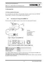
Please use a cable clip (Item /6/) for pull relief. There
are ribs (Pos. /5/) for fixing them.
(see following illustration)
5. Put the gripper to “
switch-
off position 2”.
6. Press the button
(Item /2/) briefly.
LED 2 will light up twice
7. Ready.
The sensor avoids a too small hysteresis during hystere-
sis adjustment.
The lowest securely detectable difference in stroke is
≤10 % of the nominal stroke.
the stop
Max.
10 Ncm

