background image

Design and description

4.2 Description

Compliant tool for deburring with the robot and proven deburring
tools

17

01.00 | CDB | Assembly and Operating Manual | en | 1453534

Summary of Contents for CDB

Page 1: ...Translation of Original Operating Manual Assembly and Operating Manual CDB Compliant Deburring Blade Tool...

Page 2: ...ions for the purpose of technical improvement Document number 1453534 Version 01 00 23 11 2020 en SCHUNK GmbH Co KG All rights reserved Dear Customer thank you for trusting our products and our family...

Page 3: ...rt 10 2 9 Malfunctions 10 2 10 Disposal 11 2 11 Fundamental dangers 11 2 11 1 Protection during handling and assembly 11 2 11 2 Protection during commissioning and operation 12 2 11 3 Protection again...

Page 4: ...26 7 2 Tool rattles during deburring 26 7 3 Uneven deburring result 26 7 4 Residue on the workpiece after deburring 27 7 5 Piston does not move 27 8 Maintenance 28 8 1 Notes 28 8 2 Maintenance interva...

Page 5: ...basic understanding and may differ from the actual product design In addition to these instructions the documents listed under Applicable documents 6 are applicable 1 1 1 Presentation of Warning Labe...

Page 6: ...Warranty If the product is used as intended the warranty is valid for 24 months from the ex works delivery date under the following conditions Observe the ambient conditions and operating conditions P...

Page 7: ...product is intended for installation in a machine system or for mounting to a robot The applicable guidelines must be observed and complied with The product is intended for industrial and industry ori...

Page 8: ...ized spare parts Using unauthorized spare parts can endanger personnel and damage the product or cause it to malfunction Use only original spare parts or spares authorized by SCHUNK 2 5 Ambient condit...

Page 9: ...technical training knowledge and experience trained electricians are able to work on electrical systems recognize and avoid possible dangers and know the relevant standards and regulations Qualified...

Page 10: ...nces Wear close fitting protective clothing and also wear long hair in a hairnet when dealing with moving components Wear ear protection and safety goggles during the machining process 2 8 Transport H...

Page 11: ...e energy supply is connected Do not reach into the movement area of the product during operation 2 11 1 Protection during handling and assembly Incorrect handling and assembly Incorrect handling and a...

Page 12: ...avert danger Until the installed monitors become effective it must be assumed that the drive movement is faulty with its action being dependent on the control unit and the current operating condition...

Page 13: ...ve measures to secure the danger zone WARNING Risk of injury due to unexpected movements If the power supply is switched on or residual energy remains in the system components can move unexpectedly an...

Page 14: ...l X Y 5 5 Compensation path axial Z mm 8 Compliance force N radial Min Max 25 76 Compliance force N axial Min Max 13 67 Nominal operating pressure bar Compensation air connection Air connection tool c...

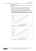
Page 15: ...n of the product The compliance pressure should be selected depending on the material of the workpiece the type of tool and the amount of material to be removed Supply pressure bar Axial compliance fo...

Page 16: ...ade Tool with manual tool change 1 Axial Connection 2 Compensation air connection 3 Housing 4 Collet 5 Axis fixation set screw Variant Auto Tool Changer Compliant Deburring Blade Tool with Auto Tool C...

Page 17: ...Design and description 4 2 Description Compliant tool for deburring with the robot and proven deburring tools 17 01 00 CDB Assembly and Operating Manual en 1453534...

Page 18: ...re that no residual energy remains in the system 1 Check the evenness of the mounting surface Mechanical connection 19 2 Connect compressed air supply line to the main air connection Pneumatic connect...

Page 19: ...irements for evenness of the mounting surface Dimensions in mm Edge length Permissible unevenness 100 0 02 100 0 05 Item Mounting CDB 1 Adapter plate provided by customer available from SCHUNK on requ...

Page 20: ...echnical data 14 Use a regulator with venting for better regulation of the compressed air NOTE Supply the tool lock air connection with compressed air continuously during use 1 Compensation air connec...

Page 21: ...roduct The locking ball unlocks 2 Push the blade holder 2 into the product and adjust the desired length The latch on the blade holder points in the direction of the locking ball 3 Loosen the manual c...

Page 22: ...1 Remove the end cap 1 from the extruded aluminum rail 4 2 Push the tool stand module 2 with the T slot into the extruded aluminum rail 4 to the desired position 3 Tighten the tool stand module 2 wit...

Page 23: ...o this distance Use the teach mode of the robot controller 1 Connect the tool lock unlock air connections 2 to the system 2 Manually actuate compressed air to unlock the tool stand module 3 Place the...

Page 24: ...en using a single axis lock only apply loads in the X direction The product must always be vertical in relation to the edge of the workpiece Orient the robot appropriately depending on the geometry of...

Page 25: ...ossible to orient the cutting tool to the workpiece contour 2 Adjust feed rate 3 Ensure that the distance to the workpiece and the orientation of the cutting tool are correctly set before each new ope...

Page 26: ...chanism at the stop Readjust the offset Operation 25 High force on initial contact with workpiece Change the feed rate and or angle when approaching the workpiece 7 2 Tool rattles during deburring Pos...

Page 27: ...iece Too much material is being removed Check process parameters reduce infeed reduce air pressure for compensation perform machining in several passes Operation 25 Workpiece is approached too fast or...

Page 28: ...oduct and or accessories SCHUNK recommends having the product and or accessories checked and repaired by SCHUNK if necessary 8 1 Notes Original spare parts Use only original spare parts of SCHUNK when...

Page 29: ...Maintenance 8 3 Assembly drawings Variant Auto Tool Changer Variant Manual tool change 29 01 00 CDB Assembly and Operating Manual en 1453534...

Page 30: ...Maintenance 30 01 00 CDB Assembly and Operating Manual en 1453534 Tool stand module...

Page 31: ......

Page 32: ...KG Clamping and gripping technology Bahnhofstr 106 134 D 74348 Lauffen Neckar Tel 49 7133 103 0 Fax 49 7133 103 2399 info de schunk com schunk com Folgen Sie uns I Follow us 11 2020 2020 SCHUNK GmbH C...

Reviews: