Assembly
25.00 | DPZ-plus | Assembly and Operating Manual | en | 389035
23
5.2 Connections
5.2.1 Mechanical connection
Evenness of the
mounting surface
The values apply to the whole mounting surface to which the
product is mounted.
Requirements for evenness of the mounting surface (Dimensions in mm)
Edge length
Permissible unevenness
< 100
< 0.02
> 100
< 0.05
Requirements for
customer adapter
plates
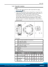
If the adapter plate has bores or recesses and therefore the
product is not fully flush, the minimum support surface must be
adhered to. The recess/bore in the adapter plate may not exceed
the dimension "A"; for dimensions, see the following table.
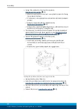
The product can be assembled from two sides.
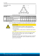
Connections at the
housing
Connections at the housing
Item Mounting
40
50
64
80
100 125 160 200
Mounting the product from the front (side A)
1 Mounting screw (3x)
M3 M3 M5 M6 M6 M8 M8 M10
Mounting the product from the rear (side B)
2 Mounting screw (3x)
-
M4 M6 M8 M8 M10 M10 M12
Max. depth of engagement from
locating surface [mm]
• without gripping force maintenance
-
10
13
17
18
21 21.5 25
Max. depth of engagement from
locating surface [mm]
• with gripping force maintenance (AS/IS)
-
20.5 26
32
38 45.5 51.5 61
3 Fitting bore for cylindrical pins *
Ø 2H7 Ø 3H7 Ø 4H7 Ø 5H7 Ø 5H7 Ø 6H7 Ø 6H7 Ø 8H7
Possible recess in the adapter plate
A Max. recess [mm]
Ø 24 Ø 32 Ø 40 Ø 55 Ø 70 Ø 85
Ø 115 Ø 150
*) Contained in accessory pack.


