background image

Assembly

26

25.00 | DPZ-plus | Assembly and Operating Manual | en | 389035

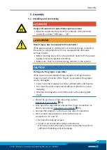
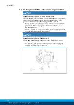
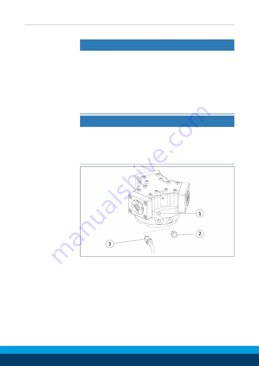
5.3 Installing the ventilation connection/air purge connection

CAUTION

Material damage due to incorrect connection!

If the product is only operated with the two main air connections,
neither correct functioning nor permanent tightness can be
guaranteed. This can result in damage to the product.

The product can only be operated if either a ventilation hose
(preferred) or the air purge has been connected at the air
purge connection.

When using the air purge connection, make sure the product
releases excess pressure while closing.

CAUTION

Material damage due to liquid ingress!

When used under water, liquid may enter the gripper during
temporary or constant immersion.

In such cases, always operate the product with air purge in
order to prevent ingress of liquid.

Summary of Contents for DPZ-plus 100

Page 1: ...Translation of the Original Manual Assembly and Operating Manual DPZ plus Sealed 3 Finger Centric Gripper ...

Page 2: ...ions for the purpose of technical improvement Document number 389035 Version 25 00 16 03 2020 en SCHUNK GmbH Co KG All rights reserved Dear Customer thank you for trusting our products and our family owned company the leading technology supplier of robots and production machines Our team is always available to answer any questions on this product and other solutions Ask us questions and challenge ...

Page 3: ...per fingers 12 2 6 Ambient conditions and operating conditions 12 2 7 Personnel qualification 12 2 8 Personal protective equipment 13 2 9 Notes on safe operation 13 2 10 Transport 14 2 11 Malfunctions 14 2 12 Disposal 14 2 13 Fundamental dangers 15 2 13 1 Protection during handling and assembly 15 2 13 2 Protection during commissioning and operation 15 2 13 3 Protection against dangerous movements...

Page 4: ...ng as desired 39 7 Maintenance 40 7 1 Notes 40 7 2 Maintenance intervals 40 7 3 Grease greasing areas 41 7 4 Threadlocker 41 7 5 Disassembly and assembly previous version 42 7 5 1 Variant without maintenance of gripping force previous version 42 7 5 2 Variantwith O D gripping maintenanceofgrippingforce previousversion 44 7 5 3 Variantwith I D gripping maintenanceofgrippingforce previousversion 50 ...

Page 5: ...Table of Contents 25 00 DPZ plus Assembly and Operating Manual en 389035 5 9 Translation of original declaration of incorporation 73 9 1 Annex to Declaration of Incorporation 74 ...

Page 6: ...ovided for basic understanding and may differ from the actual product design The product has been redesigned as of 2020 The modified successor version is directly interchangeable with the previous version and replaces it The difference between the two versions lies exclusively in the design and is therefore only relevant for spare parts such as the sealing kit The instructions identify the two ver...

Page 7: ...persons Non observance can cause minor injuries CAUTION Material damage Information about avoiding material damage 1 1 2 Applicable documents General terms of business Catalog data sheet of the purchased product Assembly and operating manuals of the accessories For ATEX versions Supplementary sheet Installation and operating instructions EX The documents marked with an asterisk can be downloaded o...

Page 8: ...intervals Observe the ambient conditions and operating conditions Parts touching the workpiece and wear parts are not included in the warranty 1 3 Scope of delivery The scope of delivery includes Sealed 3 finger centric gripper DPZ plus in the ordered model Accessory pack Content of the accessory pack 6 x Centering sleeves for mounting 2 x O ring for hose free direct connection 2 x screw plug for ...

Page 9: ...nt for spare parts such as the sealing kit The instructions identify the two versions at the relevant points with the additions previous version and successor version To distinguish between the two versions a list of all ID numbers is provided in the appendix of this manual Appendix 69 1 4 1 Seal kits Previous version ID No of the seal kit Seal kit for ID number ID number high temperature V HT DPZ...

Page 10: ... for this product Spare part package Sealing kit Successor version ID No spare part kit Sealing kit Spare part kit for Sealing kit ID number ID number high temperature V HT Ident number force intensification KVZ DPZ plus 40 1322262 1322277 DPZ plus 50 1322264 1322278 DPZ plus64 1322266 1322280 1322267 DPZ plus 80 1322269 1322281 1322270 DPZ plus 100 1322271 1322282 DPZ plus 125 1322272 1322283 DPZ...

Page 11: ...d for industrial and industry oriented use Appropriate use of the product includes compliance with all instructions in this manual 2 2 Not intended use It is not intended use if the product is used for example as a pressing tool stamping tool lifting gear guide for tools cutting tool clamping device or a drilling tool Any utilization that exceeds or differs from the appropriate use is regarded as ...

Page 12: ...s not sufficiently qualified the result may be serious injuries and significant property damage All work may only be performed by qualified personnel Before working with the product the personnel must have read and understood the complete assembly and operating manual Observe the national safety regulations and rules and general safety instructions The following personal qualifications are necessa...

Page 13: ...oggles when handling hazardous substances Wear close fitting protective clothing and also wear long hair in a hairnet when dealing with moving components 2 9 Notes on safe operation Incorrect handling of the personnel Incorrect handling and assembly may impair the product s safety and cause serious injuries and considerable material damage Avoid any manner of working that may interfere with the fu...

Page 14: ...avior in case of malfunctions Immediately remove the product from operation and report the malfunction to the responsible departments persons Order appropriately trained personnel to rectify the malfunction Do not recommission the product until the malfunction has been rectified Test the product after a malfunction to establish whether it still functions properly and no increased risks have arisen...

Page 15: ... the product s safety and cause serious injuries and considerable material damage Have all work carried out by appropriately qualified personnel For all work secure the product against accidental operation Observe the relevant accident prevention rules Use suitable assembly and transport equipment and take precautions to prevent jamming and crushing Incorrect lifting of loads Falling loads may cau...

Page 16: ...due through technical safety measures The protective cover and protective fence must be rigid enough to withstand the maximum possible movement energy EMERGENCY STOP switches must be easily and quickly accessible Before starting up the machine or automated system check that the EMERGENCY STOP system is working Prevent operation of the machine if this protective equipment does not function correctl...

Page 17: ...ive measures to secure the danger zone WARNING Risk of injury due to unexpected movements If the power supply is switched on or residual energy remains in the system components can move unexpectedly and cause serious injuries Before starting any work on the product Switch off the power supply and secure against restarting Make sure that no residual energy remains in the system WARNING Risk of inju...

Page 18: ...e unexpectedly and cause serious injuries Disassemble the product cautiously Make sure that no residual energy remains in the system WARNING Risk of injury from objects falling during energy supply failure Products with a mechanical gripping force maintenance can during energy supply failure still move independently in the direction specified by the mechanical gripping force maintenance Secure the...

Page 19: ...heet Whichever is the latest version Ambient conditions and operating conditions Designation DPZ plus Ambient temperature C min max max variant V HT 5 90 100 previous version 130 successor version IP rating with sinter filter delivery condition with venting connection with Air purge connection 54 67 68 Noise emission dB A 70 For use in dirty ambient conditions e g sprayed water vapors abrasion or ...

Page 20: ...89035 4 Design and description 4 1 Design Sealed 3 finger centric gripper 1 Housing 2 Base jaw 3 Compressed air main connection 4 Air purge connection 4 2 Description Sealed 3 finger central gripper with high gripping force and high maximum moments due to multi tooth guidance ...

Page 21: ...to the gripper is possible If the maximum permissible finger weight or the permissible mass moment of inertia of the fingers is exceeded the gripper can be damaged A jaw movement always has to be without jerks and bounce You must therefore implement sufficient reduction and or damping Observe the diagrams and information in the catalog data sheet Ø Check the evenness of the mounting surface Mechan...

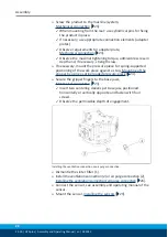
Page 22: ...g supported positioning of the work piece against a stop Mounting of the gripper by using a spring loaded pressure piece 24 Ø Secure the gripper fingers to the base jaws Mechanical connection 23 Insert two centering sleeves per base jaw positioned horizontally or vertically opposite and fasten with four screws Observe the permissible depth of engagement Installing the ventilation connection or air...

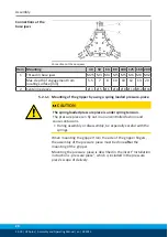
Page 23: ...ension A for dimensions see the following table The product can be assembled from two sides Connections at the housing Connections at the housing Item Mounting 40 50 64 80 100 125 160 200 Mounting the product from the front side A 1 Mounting screw 3x M3 M3 M5 M6 M6 M8 M8 M10 Mounting the product from the rear side B 2 Mounting screw 3x M4 M6 M8 M8 M10 M10 M12 Max depth of engagement from locating ...

Page 24: ...he gripper by using a spring loaded pressure piece CAUTION The spring loaded pressure piece is under spring tension The pressure piece can fly out in an uncontrolled fashion and cause contusions During assembly or disassembly be especially careful with the springs When mounting the gripper from the side of the gripper fingers the assembly of the pressure piece must be done after the mounting of th...

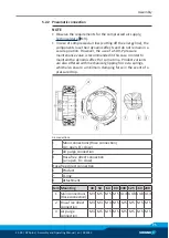
Page 25: ...ain the dynamic effect for some time Product variants are also offered with mechanical gripping force via springs which also ensure a minimum clamping force in the event of a pressure drop Air connections 1 Main connections Hose connection A open B close 2 Air purge connection 3 Hose free direct connection a open b close Hose free direct connection 6 Product 7 O ring 8 Attachment Item Mounting 40 ...

Page 26: ...ranteed This can result in damage to the product The product can only be operated if either a ventilation hose preferred or the air purge has been connected at the air purge connection When using the air purge connection make sure the product releases excess pressure while closing CAUTION Material damage due to liquid ingress When used under water liquid may enter the gripper during temporary or c...

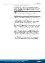
Page 27: ...the end of the hose in order to prevent ingress of foreign bodies as much as possible Fitting the air purge connection During operation using air purge excess pressure may occur If the gripper is not sufficiently relieved of excess pressure the gripper jaws may close slowly or with a jolt Excess pressure needs to be released via a pressure control valve with secondary venting see Actuation plan 1V...

Page 28: ...N 58 N 63 N 99 N 153 N 243 N 0 4 bar 24 N 35 N 40 N 77 N 84 N 132 N 204 N 324 N 0 5 bar 30 N 44 N 50 N 96 N 105 N 164 N 255 N 405 N When using air purge the gripping forces may be calculated using the following formulas The changes in gripping force using air purge from the table above are used for this Gripping force on opening FG opening FG nominal Fair purge Gripping force on closing FG closing...

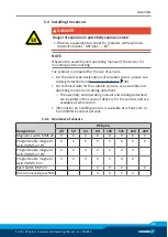
Page 29: ...nsors 30 For technical data for the suitable sensors see assembly and operating manual and catalog datasheet The assembly and operating manual and catalog datasheet are included in the scope of delivery for the sensors and are available at schunk com Information on handling sensors is available at schunk com or from SCHUNK contact persons 5 4 1 Overview of sensors Designation DPZ plus 40 50 64 80 ...

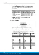
Page 30: ...jaw X 10 mm 10 of the nominal stroke per jaw Example Product with 7 mm nominal stroke per jaw 7 mm 20 1 4 mm 5 4 3 Setting dimensions Setting dimension I1 from product bottom edge 1 to front sensor 2 The setting dimension applies for the following sensors ProgrammablemagneticswitchMMS22 PI1 notforsizes50 200 ProgrammablemagneticswitchMMS22 PI2 notforsizes50 200 Programmable magnetic switch MMS P 2...

Page 31: ...of the groove Ø Pull the sensor 1 1 back again slowly until it switches Ø Secure the sensor 1 1 using the set screw 4 Tightening torque 10 Ncm Ø Bring product into the Gripper open or Part gripped position and test the function Position Gripper closed or Part gripped O D gripping Ø Bring product in the position in which it is to be set Ø If necessary remove T nut 3 Ø Turn the sensor 2 1 into the g...

Page 32: ...2 until the sensor 1 1 stops at the T nut 3 Ø Secure the sensor 1 1 using the set screw 4 Tightening torque 10 Ncm Ø Adjust sensor 1 1 see sensor assembly and operating manual Ø Repeat steps for sensor 2 Sizes 50 200 Ø Put product in the position in which it is to be set Ø Hold teaching tool to the sensor 1 1 until the sensor flashes Ø Slide sensor 1 1 into the groove 2 until the sensor 1 flashes ...

Page 33: ...aximal tightening torque NOTE If there is no T nut available slide the sensor according to dimension I1 into the groove 2 Setting dimensions 30 Ø Turn the sensor 1 into the groove 2 OR Slide the sensor 1 into the groove 2 until the sensor 1 stops at the T nut 3 Ø Secure the sensor 1 using the set screw 4 Tightening torque 10 Ncm Ø Adjust sensor 1 see sensor assembly and operating manual ...

Page 34: ...torque NOTE If there is no T nut available slide the sensor according to dimension I1 into the groove 2 Setting dimensions 30 Ø Turn the sensor 1 1 into the groove 2 OR Slide the sensor 1 1 into the groove 2 until the sensor 1 1 stops at the T nut 3 Ø Secure the sensor 1 1 using the set screw 4 Tightening torque 10 Ncm Ø Adjust sensor 1 1 see sensor assembly and operating manual Ø Repeat steps for...

Page 35: ...witches Ø Secure the sensor 1 1 using the set screw 4 Tightening torque 10 Ncm Ø Bring product into the Gripper open or Part gripped position and test the function Position Gripper closed or Part gripped O D gripping Ø Bring product in the position in which it is to be set Ø If necessary remove T nut 3 Ø Turn the sensor 2 1 into the groove 2 OR Slide sensor 2 1 into the groove 2 in the direction o...

Page 36: ...diate jaw Ø Screw gripper fingers onto the force measuring jaws 1 3 Use centering sleeves between force measuring jaw and gripper finger Ø Connect the evaluation unit see Sensor Assembly and Operating Instructions NOTE Intermediate jaws ZBA and force measuring jaws FMS are available from SCHUNK as accessories When ordering make sure that a size offset is formed between the intermediate and force m...

Page 37: ...n be moved Move the side cover 2 to the right or to the left Tighten screws 2 crosswise When the product opens and closes the side cover 2 has the correct position If the product does not open and close adjust the side cover 1 again If the product after then still does not open and close send the product to SCHUNK for repair Pressure drops below minimum Check air supply Pneumatic connection 25 Com...

Page 38: ...e mechanical guiding areas Clean and lubricate product Maintenance 40 Compressed air lines blocked Check compressed air lines of damage Mounting surface is not sufficiently flat Check the evenness of the mounting surface Excess pressure cannot be released when using air purge Check the pressure control valve with drain hole and replace if necessary Installing the ventilation connection air purge c...

Page 39: ...ir lines between the product and directional control valve as short as possible Flow rate of valve is sufficiently large relative to the compressed air consumption IMPORTANT The throttle check valve must not be removed even if the product has not reached the opening and closing times If despite optimum air connections the opening and closing times specified in the catalogue are not achieved SCHUNK...

Page 40: ... with hot surfaces causes severe burns to the skin For all work in the vicinity of hot surfaces wear safety gloves Before carrying out any work make sure that all surfaces have cooled down to the ambient temperature 7 2 Maintenance intervals Interval Mio cycles for DPZ plus Maintenance work 40 125 160 200 2 1 Clean all parts thoroughly check for damage and wear if necessary replace seals and weari...

Page 41: ...s the lubricants listed Interface Lubricant Metallic sliding surfaces Molykote BR 2 plus All seals Renolit HLT 2 Bore hole at the piston Renolit HLT 2 The guides in the housing can be re lubricated as needed Remove the set screw of the air purge connection and replace it with a lubrication nipple 7 4 Threadlocker Position of the item numbers Assembly drawing 65 Secure the screws and nuts listed in...

Page 42: ...iece Ø Unfasten and remove the screws 47 Ø Remove the cover 5 and seal 37 Ø Mark the installation positions of the piston 3 8 the base jaws 2 7 and the side cover 12 on the housing 1 Ø Unscrew and remove the screws 42 and remove the side cover 12 and the gasket 14 Ø Unscrew and remove the screws 41 and remove the cover 4 Ø Mark the installation position between the cylinder piston 60 and the housi...

Page 43: ...1 by the intermediate jaw 13 Ø Insert the gasket 14 in the housing 1 NOTE Do not damage the sealing lips of the seal 36 with the intermediate jaw 13 Ø Put on the side cover 12 making sure the installation position is correct Ø Do not screw the screw 42 completely into the cover 12 The gap between the side cover 12 and the housing 1 should be approximately divided in half Ø Allow the gripper to run...

Page 44: ...injury due to spring forces The cover is under spring tension Carefully dismantle the product Clamp the product between the housing 1 and the cover 9 in the vise so that it is still possible to remove the eight screws 46 Ø Unfasten and remove the screws 46 Ø Open the vise carefully and remove the cover 9 Ø Mark the installation position between the cylinder piston 60 and the housing 1 Ø WARNING Ri...

Page 45: ...stalled using assembly device 1 and for sizes 125 200 using assembly device 1 and 2 Assembly device for cylinder piston with maintenance of gripping force 64 Ø Push the base jaw 2 7 into the housing 1 observing the correct installation position Ø Position the base jaws 2 7 so that the piston 3 8 can be pushed into the base jaws 2 7 without any problems Ø Insert the piston 3 8 into the housing 1 fr...

Page 46: ... bore in the housing 1 NOTE Do not damage the sealing lips of the seal 30 Ø Place the cylinder piston 60 with the seal 30 on the centering bore and evenly push it into the bore hole by hand so that it pushes the spring 25 When doing this pay attention to the correct installation position Ø Tighten screw 45 Ø Remove device 1 100 Ø Insert the cylindrical pins 55 into the housing 1 Ø Fasten the cover...

Page 47: ...he side cover 12 and the housing 1 should be approximately divided in half Ø Allow the gripper to run for about 20 cycles so that the side covers 12 can be centered with respect to the base jaws 2 7 intermediate jaws 13 the gasket 14 and the housing 1 Ø Tighten the screws 42 to fasten the side cover 12 Ø Apply a strip of Plast o Seal along the side cover 12 Position of the Plast o Seal previous ve...

Page 48: ... Ø Insert spring 25 through the centering bore in the housing 1 NOTE Do not damage the sealing lips of the seal 30 Ø Place the cylinder piston 60 with the seal 30 on the centering bore and evenly push it into the bore hole by hand so that it pushes the spring 25 When doing this pay attention to the correct installation position Ø Position device 2 103 and secure to device 1 100 Ø Tighten screw 45 ...

Page 49: ...llow the gripper to run for about 20 cycles so that the side covers 12 can be centered with respect to the base jaws 2 7 intermediate jaws 13 the gasket 14 and the housing 1 Ø Tighten the screws 42 to fasten the side cover 12 Ø Apply a strip of Plast o Seal along the side cover 12 Position of the Plast o Seal previous version 53 Ø Insert the seal 37 into the housing 1 Ø Screw the cover plate 5 on ...

Page 50: ...rews 42 and remove the side cover 12 and the gasket 14 Ø WARNING Risk of injury due to spring forces The cover is under spring tension Carefully dismantle the product Clamp the product between the housing 1 and the cover 9 in the vise so that it is still possible to remove the eight screws 46 Ø Unfasten and remove the screws 46 Ø Carefully open the vise remove the cover 9 and remove the compressio...

Page 51: ... with the screws 46 NOTE The product must be in the closed position to prevent the gasket 14 from being clamped in the housing 1 by the intermediate jaw 13 Ø Insert the gasket 14 in the housing 1 NOTE Do not damage the sealing lips of the seal 36 with the intermediate jaw 13 Ø Put on the side cover 12 making sure the installation position is correct Ø Do not screw the screw 42 completely into the ...

Page 52: ...lation position between the cylinder piston 6 and the housing 1 Ø Remove the intermediate piston 66 Ø Remove the second cylinder piston 60 from the housing 1 Ø Push the pistons 3 8 upwards out of the housing 1 Ø Pull the base jaws 2 7 out of the housing 1 Assembling NOTE Tighten all screws with the required tightening torque Tightening torque for screws 64 Ø Push the base jaw 2 7 into the housing ...

Page 53: ...Do not screw the screw 42 completely into the cover 12 The gap between the side cover 12 and the housing 1 should be approximately divided in half Ø Allow the gripper to run for about 20 cycles so that the side covers 12 can be centered with respect to the base jaws 2 7 intermediate jaws 13 the gasket 14 and the housing 1 Ø Tighten the screws 42 to fasten the side cover 12 Ø Apply a strip of Plast...

Page 54: ...may leak If the filler piece 18 is disassembled however seal the filler piece 18 with liquid sealant on reassembly Ø Unscrew and remove the screws 41 and remove the cover 4 Ø Mark the installation position between the cylinder piston 61 and the housing 1 Ø Unscrew the screw 40 and remove the cylinder piston 61 from the housing 1 Ø Push the pistons 3 8 upwards out of the housing 1 NOTE Do not disas...

Page 55: ...13 Ø Put on the side cover 12 making sure the installation position is correct Ø Do not screw the screw 42 completely into the cover 12 The gap between the side cover 12 and the housing 1 should be approximately divided in half Ø Allow the product to run for about 20 cycles so that the side covers 12 can be centered with respect to the base jaws 2 7 intermediate jaws 13 Ø Tighten the screws 42 to ...

Page 56: ...uid sealant on reassembly Ø WARNING Risk of injury due to spring forces The cover is under spring tension Carefully dismantle the product Clamp the product between the housing 1 and the cover 9 in the vise so that it is still possible to remove the eight screws 46 Ø Unfasten and remove the screws 46 Ø Open the vise carefully and remove the cover 9 Ø Remove the cylindrical pins 55 Ø Mark the instal...

Page 57: ...maintenance of gripping force 64 Ø Push the base jaw 2 7 into the housing 1 observing the correct installation position Ø Position the base jaws 2 7 so that the piston 3 8 can be pushed into the base jaws 2 7 without any problems Ø Insert the piston 3 8 into the housing 1 from above Size 40 100 Fastening elements for assembly device Item Designation DPZ plus 40 50 64 80 100 100 Assembly device 1 x...

Page 58: ...centering bore in the housing 1 NOTE Do not damage the sealing lips of the seal 30 Ø Place the cylinder piston 62 with the seal 30 on the centering bore and evenly push it into the bore hole by hand so that it pushes the spring 25 When doing this pay attention to the correct installation position Ø For sizes 125 200 Position device 2 103 and secure to device 1 100 Ø Tighten screw 45 Ø For sizes 12...

Page 59: ...2 The gap between the side cover 12 and the housing 1 should be approximately divided in half Ø Allow the product to run for about 20 cycles so that the side covers 12 can be centered with respect to the base jaws 2 7 intermediate jaws 13 Ø Tighten the screws 42 to fasten the side cover 12 Ø Insert the flat seal 20 into the housing 1 Ø Screw the cover plate 5 on tight with the screws 47 Ø If neces...

Page 60: ...roduct may leak If the filler piece 18 is disassembled however seal the filler piece 18 with liquid sealant on reassembly Ø WARNING Risk of injury due to spring forces The cover is under spring tension Carefully dismantle the product Clamp the product between the housing 1 and the cover 9 in the vise so that it is still possible to remove the eight screws 46 Ø Unfasten and remove the screws 46 Ø C...

Page 61: ...on 61 over the collar Ø Insert the cylindrical pins 55 into the housing 1 Ø Insert seal 32 O rings 32 34 into the cover 9 Ø Fasten the cover 9 with the screws 46 Ø Insert the flat seal ring 39 into the side cover 12 NOTE Do not damage the sealing lips of the seal 36 with the intermediate jaw 13 Ø Put on the side cover 12 making sure the installation position is correct Ø Do not screw the screw 42 ...

Page 62: ...er piece 18 with liquid sealant on reassembly Ø Unscrew and remove the screws 41 and remove the cover 4 Ø Unscrew the screw 40 and remove the cylinder piston 6 from the intermediate housing 65 Ø Remove the intermediate housing 65 Ø Remove the cylindrical pins 55 Ø Mark the installation position between the cylinder piston 61 and the housing 1 Ø Remove the intermediate piston 66 Ø Remove the second...

Page 63: ...screw 40 Ø Insert seal 32 O rings 32 34 into the cover 4 Ø Fasten the cover 4 with screws 41 Ø Insert the flat seal ring 39 into the side cover 12 NOTE Do not damage the sealing lips of the seal 36 with the intermediate jaw 13 Ø Put on the side cover 12 making sure the installation position is correct Ø Do not screw the screw 42 completely into the cover 12 The gap between the side cover 12 and th...

Page 64: ...Item Size 40 50 64 80 100 125 160 200 40 2 2 5 9 12 12 20 49 96 150 41 0 45 1 2 1 2 1 3 1 3 7 1 7 1 7 1 42 0 8 1 35 1 35 3 1 3 1 6 1 10 26 43 2 7 5 8 14 21 42 100 200 350 45 5 8 12 14 14 29 57 5 96 200 46 0 45 1 2 1 2 2 9 2 9 6 1 6 1 26 47 1 4 1 4 1 4 1 4 2 2 2 2 2 2 4 5 7 8 Assembly device for cylinder piston with maintenance of gripping force Cylinder piston assembly device ...

Page 65: ... 5 127 5 6 M8 M8 9 20 DPZ plus 200 200 90 200 50 165 165 8 M10 M10 11 22 Type l1 0 02 l2 l3 l4 l5 l6 l7 l8 l9 l10 DPZ plus 40 36 29 9 17 25 8 6 10 DPZ plus 50 45 41 2 22 11 10 DPZ plus 64 56 48 5 28 14 20 DPZ plus 80 70 60 6 35 17 5 20 DPZ plus 100 90 78 45 22 5 20 DPZ plus 125 112 97 56 56 97 28 20 112 30 45 DPZ plus 160 146 126 4 73 73 126 4 36 5 20 146 30 55 DPZ plus 200 184 159 3 92 92 159 3 4...

Page 66: ...ipping I D gripping without maintenance of gripping force previous version 1 Wearing part replace during maintenance Included in the seal kit Seal kit can only be ordered completely 2 Positions are adapted to each other and can not be replaced by the customer 3 for sizes 40 and from 125 4 from size 160 ...

Page 67: ...pping I D gripping without maintenance of gripping force successor version 1 Wearing part replace during maintenance Included in the seal kit Seal kit can only be ordered completely 2 Positions are adapted to each other and can not be replaced by the customer 3 for sizes 40 and from 125 4 from size 160 ...

Page 68: ... with force intensification cylinder previous version successor version Wearing part replace during maintenance Included in the seal kit Seal kit can only be ordered completely Gripper variants with force intensification cylinders are not permitted for use in explosion protected applications EX ...

Page 69: ...dditions previous version and successor version DPZ plus Ident number Previous version Ident number Successor version 40 304501 1316263 40 1 AS EX 305221 1315367 40 1 EX 305220 1315361 40 1 IS EX 305222 1315369 40 AS 304503 1316265 40 AS V 1321292 40 IS 304505 1316267 40 IS V 39304505 1321293 40 V 39304501 1321291 50 1 304401 1316268 50 1 AS 304403 1316272 50 1 AS EX 305232 1315379 50 1 AS V 13212...

Page 70: ...4414 1316284 64 2 AS EX 305243 1315459 64 2 AS V 1417451 1321313 64 2 EX 305241 1315402 64 2 IS 304416 1316287 64 2 IS EX 305245 1315468 64 2 IS V 1417452 1321319 64 2 V 39304412 1321311 80 1 304421 1316288 80 1 AS 304423 1316291 80 1 AS EX 305252 1315478 80 1 AS V 1321323 80 1 EX 305250 1315473 80 1 IS 304425 1316293 80 1 IS EX 305254 1315485 80 1 IS V 1321325 80 1 KVZ 304427 1316289 80 1 V 39304...

Page 71: ... AS EX 305263 1315504 100 2 AS V 1321334 100 2 EX 305261 1315492 100 2 IS 304436 1316302 100 2 IS EX 305265 1315509 100 2 IS V 39304436 1321340 100 2 V 39304432 1321331 125 1 304441 1316303 125 1 AS 304443 1316306 125 1 AS EX 305272 1315514 125 1 AS V 39304443 1321343 125 1 EX 305270 1315510 125 1 IS 304445 1316308 125 1 IS EX 305274 1315520 125 1 IS V 39304445 1321345 125 1 V 39304441 1321341 125...

Page 72: ... 2 AS EX 305283 1315541 160 2 AS V 1414841 1321352 160 2 EX 305281 1315529 160 2 IS 304456 1316316 160 2 IS EX 305285 1315546 160 2 IS V 1321355 160 2 V 1377891 1321350 200 1 304461 1316317 200 1 AS 304463 1316320 200 1 AS EX 305292 1315550 200 1 AS V 39304463 1321358 200 1 EX 305290 1315548 200 1 IS 304465 1316322 200 1 IS EX 305294 1315552 200 1 IS V 1321361 200 1 V 39304461 1321356 200 2 304462...

Page 73: ...n Sealed 3 finger centric gripper DPZ plus pneumatic ID number 0304401 0304466 The partly completed machine may not be put into operation until conformity of the machine into which the partly completed machine is to be installed with the provisions of the Machinery Directive 2006 42 EC is confirmed Applied harmonized standards especially EN ISO 12100 2010 Safety of machinery General principles for...

Page 74: ...nciples of safety integration X 1 1 3 Materials and products X 1 1 4 Lighting X 1 1 5 Design of machinery to facilitate its handling X 1 1 6 Ergonomics X 1 1 7 Operating positions X 1 1 8 Seating X 1 2 Control Systems 1 2 1 Safety and reliability of control systems X 1 2 2 Control devices X 1 2 3 Starting X 1 2 4 Stopping X 1 2 4 1 Normal stop X 1 2 4 2 Operational stop X 1 2 4 3 Emergency stop X ...

Page 75: ... Adjustable guards restricting access X 1 4 3 Special requirements for protective devices X 1 5 Risks due to other hazards 1 5 1 Electricity supply X 1 5 2 Static electricity X 1 5 3 Energy supply other than electricity X 1 5 4 Errors of fitting X 1 5 5 Extreme temperatures X 1 5 6 Fire X 1 5 7 Explosion X 1 5 8 Noise X 1 5 9 Vibrations X 1 5 10 Radiation X 1 5 11 External radiation X 1 5 12 Laser...

Page 76: ...safety requirements for certain categories of machinery X 2 1 Foodstuffs machinery and machinery for cosmetics or pharmaceutical products X 2 2 Portable hand held and or guided machinery X 2 2 1 Portable fixing and other impact machinery X 2 3 Machinery for working wood and material with similar physical characteristics X 3 Supplementary essential health and safety requirements to offset hazards d...

Reviews: