Design and description
24
04.00 - FW 2.x | EGL | Assembly and Operating Manual | en | 389661
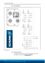
4.3 Interfaces and service windows
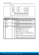
Interfaces and service window, PROFIBUS and CAN bus variant
Ite
m
Designation
Function
1
PROFIBUS or CAN bus connector
Communication input
2
Rotary encoding switch
Address configuration for PROFIBUS or
CAN bus
3
LED
Status display and error analysis
4
USB Micro AB, host*
Firmware update via USB flash drive
5
Voltage supply connector
Logic and power supply
6
USB mini AB, device*, parameterized
interface
Service interface, parameterization and
firmware update via computer
7
Logic supply fuse
Protection for logic supply,
1 A, time delay
8
DIP switch
Testing and commissioning functions,
adjustment of baud rate for CAN bus
9
PROFIBUS or CAN bus socket
Communication output
or termination resistor
*)
IMPORTANT! Do not load the USB interface from the side as it
may be damaged.

