background image

Basic safety notes

12

02.00 | ELM | Assembly and operating manual | en | 389058

2.11 Disposal

Handling of disposal

The incorrect handling of disposal may impair the product's safety
and cause serious injuries as well as considerable material and
environmental harm.
• Follow local regulations on dispatching product components for

recycling or proper disposal.

2.12 Fundamental dangers

General

• Observe safety distances.
• Never deactivate safety devices.
• Before commissioning the product, take appropriate protective

measures to secure the danger zone.

• Disconnect power sources before installation, modification,

maintenance, or calibration. Ensure that no residual energy
remains in the system.

• If the energy supply is connected, do not move any parts by

hand.

• Do not reach into the open mechanism or movement area of

the product during operation.

2.12.1 Protection during handling and assembly

Incorrect handling and assembly

Incorrect handling and assembly may impair the product's safety
and cause serious injuries and considerable material damage.
• Have all work carried out by appropriately qualified personnel.
• For all work, secure the product against accidental operation.
• Observe the relevant accident prevention rules.
• Use suitable assembly and transport equipment and take

precautions to prevent jamming and crushing.

Incorrect lifting of loads

Falling loads may cause serious injuries and even death.
• Stand clear of suspended loads and do not step into their

swiveling range.

• Never move loads without supervision.
• Do not leave suspended loads unattended.

Summary of Contents for ELM 23-H70

Page 1: ...Translation of the original manual Assembly and operating manual ELM Linear axis...

Page 2: ...tions for the purpose of technical improvement Document number 389058 Version 02 00 24 06 2019 en SCHUNK GmbH Co KG All rights reserved Dear Customer thank you for trusting our products and our family...

Page 3: ...8 2 Basic safety notes 9 2 1 Intended use 9 2 2 Not intended use 9 2 3 Constructional changes 9 2 4 Spare parts 9 2 5 Ambient conditions and operating conditions 9 2 6 Personnel qualification 10 2 7 P...

Page 4: ...Mounting of cover MA 28 5 Troubleshooting 29 5 1 Modul bewegt sich nicht 29 5 2 The module does not travel through the entire stroke 29 5 3 Electric signals are not transmitted 29 5 4 Motor temperatur...

Page 5: ...manual Illustrations in this manual are provided for basic understanding and may differ from the actual product design In addition to these instructions the documents listed under Applicable document...

Page 6: ...rts are not included in the warranty 1 3 Scope of delivery The scope of delivery includes Linear axis ELM in the version ordered Assembly and Operating Manual Accessory pack 1 4 Accessories The follow...

Page 7: ...accuracy Designation Type ID Position measuring system for ELM 23 70 WSM 23 070 0314112 Position measuring system for ELM 37 160 WSM 37 160 0314113 Position measuring system for ELM 37 260 WSM 37 260...

Page 8: ...the sense of the Machine Directive The module is optionally available with a rod lock to prevent mechanical damage in the event of malfunctions Description Type ID Rod lock for ELM 23 70 ASP E 23 070...

Page 9: ...le as a pressing tool stamping tool lifting gear guide for tools cutting tool clamping device or a drilling tool Any utilization that exceeds or differs from the appropriate use is regarded as misuse...

Page 10: ...d tasks recognize and avoid possible dangers and knows the relevant standards and regulations Instructed person Instructed persons were instructed by the operator about the delegated tasks and possibl...

Page 11: ...vention and environmental protection regulations regarding the product s application field 2 9 Transport Handling during transport Incorrect handling during transport may impair the product s safety a...

Page 12: ...system If the energy supply is connected do not move any parts by hand Do not reach into the open mechanism or movement area of the product during operation 2 12 1 Protection during handling and asse...

Page 13: ...trigger dangerous movements Never rely solely on the response of the monitoring function to avert danger Until the installed monitors become effective it must be assumed that the drive movement is fa...

Page 14: ...af aids Pregnant women The above mentioned persons must always keep a safe distance of at least 2 m from the product DANGER Danger from electric voltage Touching live parts may result in death Switch...

Page 15: ...no residual energy remains in the system WARNING Risk of injury from sharp edges and corners Sharp edges and corners can cause cuts Use suitable protective equipment WARNING Risk of burns through cont...

Page 16: ...r temperature C 65 65 65 Max driving force N 60 160 160 Max rated constant force with us of fan cooling N 31 100 100 Repeat accuracy more exact positioning through accessory position measuring system...

Page 17: ...H160 ASP ELM 37 H260 ASP Weight kg 1 61 5 25 5 83 Minimum release pressure bar 3 3 3 Static holding force N 180 350 350 Max axial play of clamp mm 0 2 0 25 0 25 3 3 Fan cooling MK 23 MK 37 Nominal vo...

Page 18: ...system Switch off energy supply Evenness of the mounting surface The values apply to the whole mounting surface to which the product is mounted Requirements for evenness of the mounting surface Dimen...

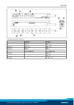
Page 19: ...ly 02 00 ELM Assembly and operating manual en 389058 19 Connection geometries for ELM 37 ELM 23 ELM 37 A M5 7 M5 10 B mm 5F7 7 5F7 3 C mm 3F7 5F7 D Km4 DIN974 1 Km5 DIN974 1 E mm 5F7 5 F M5 9 G mm 12...

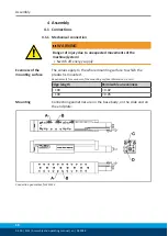
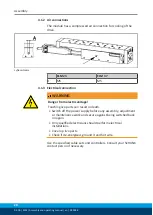
Page 20: ...G Danger from electric voltage Touching live parts can result in death Switch off the power supply before any assembly adjustment or maintenance work and secure against being switched back on again On...

Page 21: ...from magnetic tape mm 0 3 0 1 0 3 0 1 B Position of magnetic tape mm 7 27 5 The bolting surfaces must be clean and undamaged and the support surface for the magnetic tape must be free of dirt and grea...

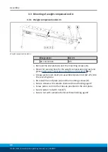
Page 22: ...the receiving bore for the weight compensation arrow and grease Lubricants lubrication points basic lubrication 32 Grease piston and insert pre assembled piston rod 02 05 into the receiving bore Re i...

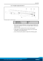
Page 23: ...nnection M5 Place the pneumatic cylinder 1 in the opening provided in the base body and clamp it on the cover plate between the disk 2 and the nut 3 Secure nut with suitable chemical thread locking ag...

Page 24: ...ELM 23 ELM 37 A Shock absorber SD 23 SD 37 Screw shock absorbers into the threads provided Secure shock absorbers with nuts NOTE The module conducts the reference run only at a certain force During th...

Page 25: ...n the product has been shut down See the data on static holding force in the catalog The forces occurring in a clamped condition must not exceed the holding force In the event of a dynamic load or ove...

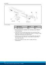
Page 26: ...B from the ELM module Mount the pre assembled base body unit consisting of base body 8 rod lock 7 and sliding bushing 6 on the body of ELM using the cylindrical screws 5 provided Mount the pre assembl...

Page 27: ...Designation MK 23 MK 37 1 Spacer 5mm 4 6 2 Compact fan 2 3 3 Protective grid 2 3 4 Mounting screw ISO 4762 M4x35 4 6 Bolt compact fan 2 and protective grid 3 to the module using mounting screws 4 Use...

Page 28: ...00 ELM Assembly and operating manual en 389058 4 7 Mounting of cover MA Mounting of cover Mount cover 2 on the slide using mounting screws 1 and spacers 3 Secure threads with suitable chemical thread...

Page 29: ...nts lubrication points basic lubrication 32 and Removing and cleaning rotor 33 Mounting surface is not sufficiently flat Check the evenness of the mounting surface Mechanical connection 18 Components...

Page 30: ...signed for the requirements Check design Consult your SCHUNK contact person 5 6 Required precision is not reached M gliche Ursache Ma nahmen zur Behebung The module is not designed for the requirement...

Page 31: ...ectedly and cause serious injuries Before starting any work on the product Switch off the power supply and secure against restarting Make sure that no residual energy remains in the system 6 1 Mainten...

Page 32: ...basic lubrication We recommend the lubricants listed here Equivalent lubri cants can also be used Lubricant point Lubricant Rotor LU02 from Linmot or UH1 14 31 from Kl ber Guide carriage ISOFLEX TOPA...

Page 33: ...otor 3 back out of the stator 4 Clean rotor 3 and inner surface of stator 4 with a soft cloth and alcohol Lubricate rotor previous Tab and carefully insert it in the stator Fasten rotor with mounting...

Page 34: ...quired for disassembly assembly of the module In case of damage and malfunctions we recommend sending the module to the factory for repair In case of unauthorized disassembly assembly of the module th...

Page 35: ...Maintenance and care 02 00 ELM Assembly and operating manual en 389058 35 6 5 Assembly drawings 6 5 1 Assembly of ELM 23 Assembly of ELM 23...

Page 36: ...Maintenance and care 36 02 00 ELM Assembly and operating manual en 389058 6 5 2 Assembly of ELM 37 Assembly of ELM 37...

Page 37: ...r 0314365 0314366 0314367 0314368 0314369 0314370 0314371 0314372 0314373 0314374 0314380 0314381 The partly completed machine may not be put into operation until conformity of the machine into which...

Page 38: ...1 Essential Requirements 1 1 1 Definitions X 1 1 2 Principles of safety integration X 1 1 3 Materials and products X 1 1 4 Lighting X 1 1 5 Design of machinery to facilitate its handling X 1 1 6 Ergon...

Page 39: ...g movable guards X 1 4 2 3 Adjustable guards restricting access X 1 4 3 Special requirements for protective devices X 1 5 Risks due to other hazards 1 5 1 Electricity supply X 1 5 2 Static electricity...

Page 40: ...ty requirements for certain categories of machinery X 2 1 Foodstuffs machinery and machinery for cosmetics or pharmaceutical products X 2 2 Portable hand held and or guided machinery X 2 2 1 Portable...

Reviews: