background image

Troubleshooting

24

03.00 | GM 80 – 201 | Assembly and Operating Manual | en | 389092

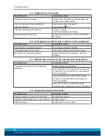
6.5 Gripping force is dropping

Possible cause

Corrective action

Compressed air can escape.

Check seals, if necessary, disassemble the
product and replace seals.

Too much grease in the mechanical
movement space.

Clean and lubricate product.

Maintenance

 [

}

 25]

Pressure drops below minimum.

Check air supply.
Link Pneumatischer Anschluss

Component part defective.

Replace component or send it to SCHUNK
for repair.

6.6 Is the gripper not able to grip or hold on to the workpiece?

Possible cause

Corrective action

The workpiece weighs too much

Use a larger gripping module

The gripper jaws are too long

Place the gripping point further inside

Non-optimal engineering design

Adapt the engineering design – form-fit
gripping

6.7 Module does not achieve the opening and closing times?

Possible cause

Corrective action

Compressed air lines are not installed
optimally.

Check compressed air lines.
Inner diameters of compressed air lines are
of sufficient size in relation to compressed
air consumption.
Keep compressed air lines between the
product and directional control valve as
short as possible.
Flow rate of valve is sufficiently large
relative to the compressed air consumption.

6.8 End position signal not present?

Possible cause

Corrective action

Precisely adjust the sensor for the stop

Readjust the sensor

Proximity switch defective or set incorrect.

Replace sensor

Cable breakage

Replacing the sensor cable

Summary of Contents for GM 100

Page 1: ...Translation of Original operating manual Assembly and Operating Manual GM 80 201 2 finger parallel gripper...

Page 2: ...erations for the purpose of technical improvement Document number 389092 Version 03 00 11 02 2019 en SCHUNK GmbH Co KG All rights reserved Dear Customer thank you for trusting our products and our fam...

Page 3: ...ditions 9 2 7 Personnel qualification 10 2 8 Personal protective equipment 11 2 9 Notes on safe operation 11 2 10 Transport 12 2 11 Malfunctions 12 2 12 Disposal 12 2 13 Fundamental dangers 13 2 13 1...

Page 4: ...orce is dropping 24 6 6 Is the gripper not able to grip or hold on to the workpiece 24 6 7 Module does not achieve the opening and closing times 24 6 8 End position signal not present 24 7 Maintenance...

Page 5: ...his manual Illustrations in this manual are provided for basic understanding and may differ from the actual product design In addition to these instructions the documents listed under Applicable docum...

Page 6: ...thout gripping force maintenance GM with gripping force maintenance O D gripping K GM with gripping force maintenance I D gripping S 1 2 Warranty If the product is used as intended the warranty is val...

Page 7: ...earing parts sets All the seals are included in their scope of delivery ID No of the seal kit Seal kit for Designation ID number GM 80 81 GMDI 080 0313448 GM 100 101 GMDI 100 0313450 GM 200 201 GMDI 2...

Page 8: ...on in a machine system The applicable guidelines must be observed and complied with The product is intended for industrial and industry oriented use Appropriate use of the product includes compliance...

Page 9: ...or the application 2 6 Environmental and operating conditions Required ambient conditions and operating conditions Incorrect ambient and operating conditions can make the product unsafe leading to the...

Page 10: ...related to the product Trained electrician Due to their technical training knowledge and experience trained electricians are able to work on electrical systems recognize and avoid possible dangers an...

Page 11: ...oggles when handling hazardous substances Wear close fitting protective clothing and also wear long hair in a hairnet when dealing with moving components 2 9 Notes on safe operation Incorrect handling...

Page 12: ...avior in case of malfunctions Immediately remove the product from operation and report the malfunction to the responsible departments persons Order appropriately trained personnel to rectify the malfu...

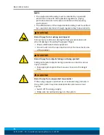
Page 13: ...oduct during operation 2 13 1 Protection during handling and assembly Incorrect handling and assembly Incorrect handling and assembly may impair the product s safety and cause serious injuries and con...

Page 14: ...to avert danger Until the installed monitors become effective it must be assumed that the drive movement is faulty with its action being dependent on the control unit and the current operating conditi...

Page 15: ...ements 2 14 Notes on particular risks Generally valid Remove the energy supplies before installation modification maintenance or adjustment work Make sure that no residual energy remains in the system...

Page 16: ...y could occur during the base jaw procedure and when breaking or loosening the gripper fingers Wear suitable protective equipment Do not reach into the open mechanism or the movement area of the produ...

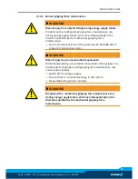
Page 17: ...the end positions of the product with SCHUNK SDV P pressure maintenance valves WARNING Risk of injury due to uncontrolled movements While disassembling uncontrolled movements of the gripper s in divid...

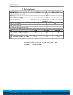
Page 18: ...A 70 Pressure medium Compressed air compressed air quality according to ISO 8573 1 7 4 4 Min pressure bar 3 4 5 Max pressure bar 8 Nominal working pressure bar 6 Size 80 81 100 101 200 201 Max permiss...

Page 19: ...ions for the position and size of the connection geometries Catalog data sheet of the product Mounting Mount the module using the fixing bores provided Mount the modules using the fixing bores provide...

Page 20: ...Pressure medium The unit must not under any circumstances be operated with oiled air before operation with unoiled air washing out of factory lubrication 4 3 Stroke adjustment of the gripper jaws For...

Page 21: ...talog the spring will have already been installed by SCHUNK 4 5 End position monitoring To monitor the end positions standardized monitoring sets for direct installation are available The installation...

Page 22: ...ation has been checked taking all permissible operating parameters into account The movement speed is ideally regulated via throttle check valves Air connection 20 The speed is always set so that it s...

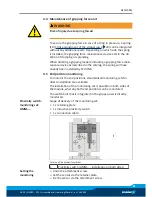
Page 23: ...in the mechanical elements Clean and lubricate product Maintenance 25 Pressure drops below minimum Check air supply Air connection 20 Mounting surface is not sufficiently flat Check the evenness of th...

Page 24: ...he gripper jaws are too long Place the gripping point further inside Non optimal engineering design Adapt the engineering design form fit gripping 6 7 Module does not achieve the opening and closing t...

Page 25: ...bricant with a lint free cloth Lubricant point Lubricant Lever mechanism connecting member other mechanical slid ing points Isoflex Topas NCA 52 Fa Kl ber All seals Bore hole at the piston Only after...

Page 26: ...tightening torque when assembling the product or loads on the product in accordance with the generally accepted guidelines for screw connections Secure all screws using a suitable chemical screw lock...

Page 27: ...ves for illustration and assignment of the spare parts Variations are possible depending on size and variant All other wearing parts and individual components are available individually according to t...

Page 28: ...3061 0313062 0313063 0313064 0313065 0313096 0313070 0313071 0313072 0313073 0313074 0313078 0313079 0313080 0313081 0313082 0313083 The partly completed machine may not be put into operation until co...

Page 29: ...81 0313082 0313083 To be provided by the System Integrator for the overall machine Fulfilled for the scope of the partly completed machine Not relevant 1 1 Essential Requirements 1 1 1 Definitions X 1...

Page 30: ...isks of uncontrolled movements X 1 4 Required characteristics of guards and protective devices 1 4 1 General requirements X 1 4 2 Special requirements for guards X 1 4 2 1 Fixed guards X 1 4 2 2 Inter...

Page 31: ...tion from Annex 1 is to be supplemented from here forward 2 Supplementary essential health and safety requirements for certain categories of machinery X 2 1 Foodstuffs machinery and machinery for cosm...

Page 32: ...32 03 00 GM 80 201 Assembly and Operating Manual en 389092...

Reviews: